18
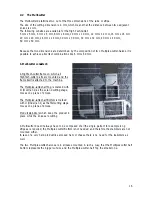
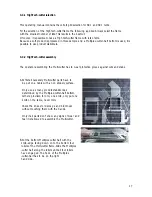
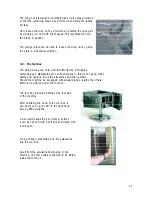
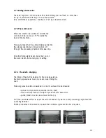
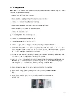
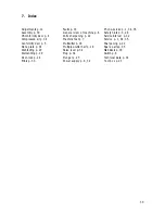
C. Now the product stabilizer(s) have to be inserted
into the Multi-cutter frame from the side, on top of
the knives of the bottom Multiplex-cutter-half.
The stabilizers are inserted so far, that they are
not protruding on either side of the Multi-cutter
frame. In case of no Multiplex-cutter-half bottom,
no product stabilizer is inserted.
This applies also, when there is no stabilizer
support in the Multi-cutter frame.
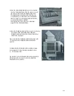
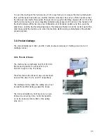
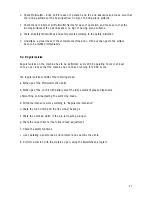
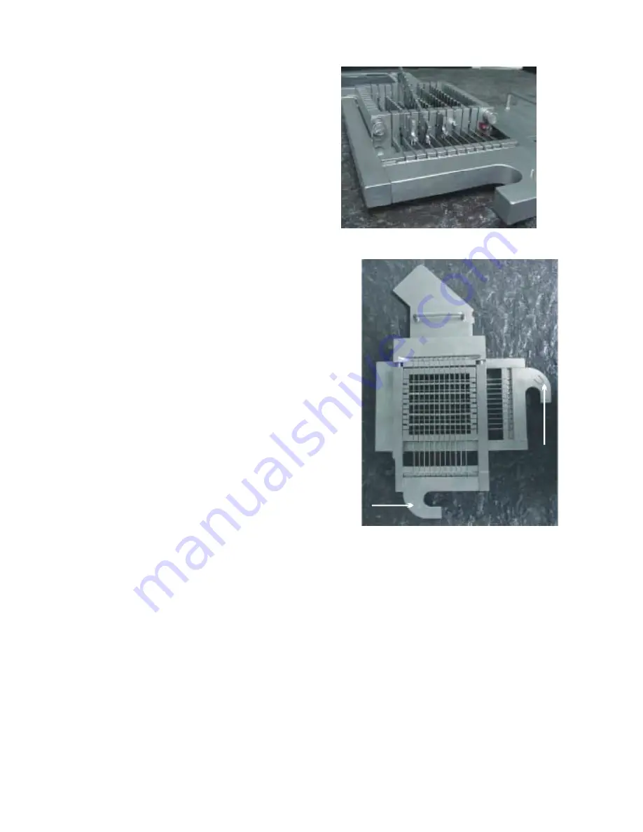
D. Now the Multiplex-cutter-half top is put on to the top
four rollers of the Multi-cutter frame. Slide the
Multiplex-cutter-half along the rollers, until all four
rollers have engaged.
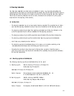
Take note that the Multiplex-cutter-half marked with
”U” lies behind the Multiplex-cutter-half marked
with ”O”.
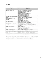
To dismantle the Multi-cutter after a cutting process,
it is necessary to follow the steps described under
A – D in reverse order.
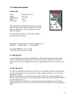
The handle on the Multi-cutter allows the operator to
lift it slowly with one hand in order to attach the
Multi-cutter to the machine.
!
!
Summary of Contents for SR1 turbo
Page 5: ...5...

