Section 03 787 RFI ENGINE
Subsection 01 (LEAK TEST)
Engine Cooling System
Remove the exhaust manifold gasket and ensure
the surface is clean.
Install the appropriate exhaust manifold plate from
the engine leak test kit (P/N 295 500 352). Tighten
plate using fasteners provided in the kit.
NOTE:
Do not torque plate excessively.
Install a small hose pincher (P/N 295 000 076) on
engine drain hose.
295 000 076
Use hoses provided in the kit and install them on
the engine.
Install pump using reducer and appropriate tube(s)
as necessary.
3
2
1
F02E0DA
REAR VIEW
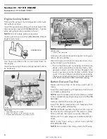
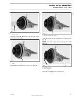
1. Loop hose and use clamps
2. Hose with clamps. Install pump to the end
3. Block engine drain hose with a hose pincher
F02D0WA
1
FRONT VIEW
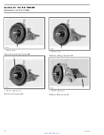
1. Exhaust manifold plate
Activate pump and pressurize engine cooling sys-
tem to 34 kPa (5 PSI).
Wait 3 minutes and check if pressure drops; if so,
verify all testing components.
– If kit components are not leaking and pressure
drops, verify all external jointed surfaces, tem-
perature sensor and the O-ring between the
spark plug area and the engine cylinder head
cover. If none of these components are leaking,
there is an internal leak and it can be detected
with BOTTOM END AND TOP END testing.
Bottom End and Top End
Make sure the surface of the rotary valve cover is
clean.
Install the intake plates with fasteners from the kit
and tighten adequately.
NOTE:
Use the intake and exhaust plates included
in the supplementary engine leak test kit (P/N 295
500 780).
Remove the RAVE valves and gaskets.
Install the RAVE valve plates with fasteners from
the kit and tighten adequately.
NOTE:
On RAVE system, the boot and O-ring can
be checked for leakage with the valve in place.
Simply remove the cover to expose the parts.
Make sure the spark plugs are installed and tight-
ened.
Block pulse hose using a small hose pincher
(P/N 295 000 076).
NOTE:
Do not block the rotary valve shaft hoses.
60
smr2005-080
www.SeaDooManuals.net

