Section 03 787 RFI ENGINE
Subsection 03 (TOP END)
F01D8LA
Cylinder Base Gasket
NOTE:
The general procedure is to install a new
gasket of the same thickness. However, if you do
not know the gasket thickness that was installed
or if a crank repair has involved replacement of
connecting rods, refer to COMBUSTION CHAM-
BER VOLUME MEASUREMENT in ENGINE MEA-
SUREMENT section to properly determine the re-
quired gasket thickness.
Different thicknesses of cylinder base gaskets are
used for a precise adjustment of the combustion
chamber volume.
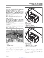
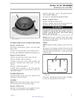
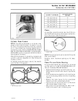
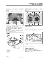
To identify gasket thickness, refer to the identifi-
cation holes on the gasket.
F01D67A
1
TYPICAL
1. Identification holes
GASKET THICKNESS
IDENTIFICATION
HOLES
0.3 mm (.012 in)
3
0.4 mm (.016 in)
4
0.5 mm (.020 in)
5
0.6 mm (.024 in)
6
0.8 mm (.031 in)
8
Piston
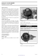
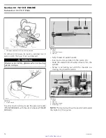
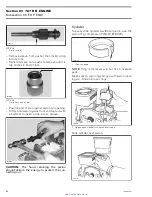
At assembly, place the pistons
no. 3
with the let-
ters
″
AUS
″
(over an arrow on the piston dome) fac-
ing in direction of the exhaust port.
A01C01A
AUS
1
1. Exhaust side
NOTE:
The exhaust ports are located on the same
side as the intake.
Carefully cover crankcase opening as for disas-
sembly.
Piston Pin and Roller Bearing
To install roller bearing
no. 4
and piston pin
no. 6
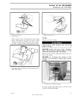
use the piston pin puller (P/N 529 035 503) with
the set of sleeves (P/N 529 035 542).
– Replacement bearings are held in place by a lo-
cating sleeve outside and 2 plastic cage halves
inside.
– Push needle bearing together with inner halves
out of the locating sleeve into the connecting
rod bore.
– Replace the inner halves by the appropriate
sleeve tool in the connecting rod bore.
– Insert piston pin into piston until it comes flush
with inward edge of piston hub.
– Warm piston to approximately 50 - 60°C (122 -
140°F) and install it over connecting rod.
smr2005-082
81
www.SeaDooManuals.net

