Section 02 717 ENGINE
Subsection 04 (BOTTOM END)
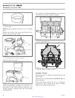
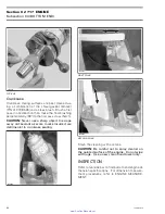
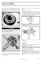
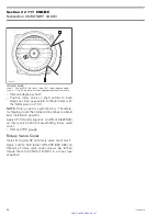
Touch the inner race of the bearing with the tem-
perature indicator stick (P/N 529 035 970). Stick
will liquefy when the bearing reach the proper
temperature.
A32CB9A
TYPICAL
WARNING
Do not touch heated bearing with bare han-
dle. Wear heat resisting gloves before han-
dling the heated bearing(s).
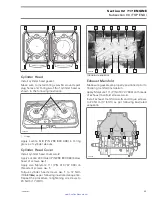
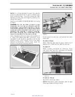
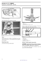
Smear Loctite 767 (antiseize lubricant) (P/N 293
800 070) on part of crankshaft where bearing fits.
A32CB6A
TYPICAL
Install the distance ring
no. 12
. Make sure to posi-
tion it with its chamfer toward the counterweight
of the crankshaft.
Slide in the inner bearing. Push bearing to end
position.
Install the retaining disk.
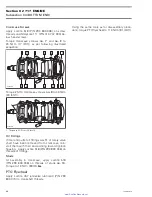
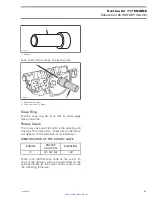
To properly position the outer bearing(s), the dis-
tance gauge (P/N 529 034 800) must be temporar-
ily installed against the inner bearing. Slide the
outer bearing until stopped by the distance gauge,
then remove the distance gauge.
F01B0HA
1
1. Distance gauge
F01D1YA
1
2
TYPICAL
1. Distance gauge
2. Outer bearing
Crankcase
NOTE:
Rotary valve shaft must be installed in
crankcase before closing halves.
CAUTION:
Before joining crankcase halves,
make sure that crankshaft gear is well engaged
with rotary valve shaft gear.
Crankcase Sealant Application
IMPORTANT:
When beginning the application of
the crankcase sealant, the assembly and the first
torquing should be done within 10 minutes. It is
suggested to have all you need on hand to save
time.
44
smr2005-078
www.SeaDooManuals.net

