background image

Output

Switcher

Input

576i 50Hz

576i 50Hz

576i 50Hz

1080p 50Hz (A or

B)

1080i 50Hz

1080i 50Hz

720p 50Hz

480i 59.94Hz

480i 59.94Hz

480i 59.94Hz

1080p 59.94Hz (A

or B)

1080i 59.94Hz

1080i 59.94Hz

720p 59.94Hz

Notes

1

Converted using either a simple

line-doubler or 4-line interpolater and may

result in lower quality video.

2

Converted by dropping frames and may

result in lower quality video.

3

Only inputs 3-6 and 8-11 support Quad

3Gb/s or 1.5Gb/s UHDTV1 video.

4

Conversion is not supported when the

switcher is operating in this video format.

Input FSFC

Assign an FSFC to an input and then set up how

the FSFC is used on the input.

To Assign an FSFC to an Input (UHDTV1 Only)

You must assign an FSFC to an input to convert

the input video. The CUF-ADD-I/OPLUS option

provides additional resources.

1.

Click

Navigation Menu

>

Configuration

>

Reference

.

2.

In the

Input FSFC Assignment

area, click

the

Input FSFC X

button for the FSFC you

want to use.

3.

Click the

Input

button to select the video

input that you want to assign the FSFC to.

Tip:

Click Off to take the FSFC out of the video path for the

selected input.

To Set Up an Input FSFC (SD or HD Only)

In SD or HD, configure the FSFC that has been

assigned to the input. The conversion that is

available depends on the format the switcher

is operating in and the input that is being

converted.

Note:

If you do not have the CUF-ADD-I/OPLUS option activated,

an I/O Processor must be assigned to the input first.

1.

Click

Navigation Menu

>

Configuration

>

Inputs

>

External

.

2.

Click the

Configure

button for the input you

want to assign an FSFC to.

3.

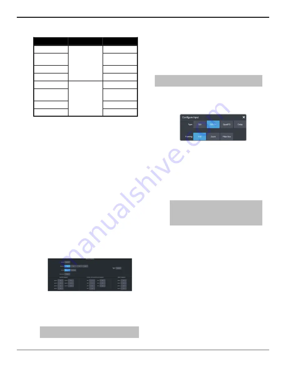
Click a

Type

button to turn on the FSFC.

SDI

— no FSFC is applied to the input.

SDI-FS

— an FSFC is applied to the input.

QuadFS

— a timed FSFC is applied to the

input. Each QuadFS is timed to the first

SDI-FS in the group of four (1-4, 5-8, 9-12).

The SDI-FS must be applied to the first

input and QuadFS to the rest of the inputs

in the group.

Tip:

Use this if you are taking the quad-split output

from an untimed UHD camera that you need to

frame-sync. The frame syncs applied to each input are

locked together for timing so that all four inputs are in

sync.

4.

If required, select the aspect ratio

conversion mode you want to use.
The options that are available depend on

the video format that the switcher is

converting from and to.

Full

— The video signal is scaled

disproportionately to fill the display of

the new aspect ratio. Aspect distortion

occurs as the image is

stretched/compressed to fit in the new

aspect ratio.

Zoom

— The central portion of the video

signal is zoomed to fill the display of the

new video format. No aspect distortion

is introduced but the edges of the video

signal may be cropped.

Letter Box

— Black bars are added to the

top and bottom of a 16:9 image to display

correctly in a 4:3 video format.

96 • Frame Sync and Format Conversion — Ultra User Manual (v6.6)

Summary of Contents for Carbonite Ultra Series

Page 1: ...Ultra User Manual v6 6...

Page 2: ...en At Ross our employees are a special group Our employees truly care about doing a great job and delivering a high quality customer experience every day This code of ethics hangs on the wall of all R...

Page 3: ...pecific equipment and or installation procedures to be carried out to satisfy certain regulatory compliance requirements Notices have been included in this publication to call attention to these speci...

Page 4: ...idual supply cord is connected to its own separate branch circuit with an earth connection 20 CAUTION These service instructions are for use by qualified service personnel only To reduce the risk of e...

Page 5: ...ipment is in compliance with the essential requirements and other relevant provisions of CE Directive 93 68 EEC International This equipment has been tested to CISPR 22 1997 along with amendments A1 2...

Page 6: ...and health conscious manner The crossed out wheeled bin symbol invites you to use these systems If you need more information on the collection reuse and recycling systems please contact your local or...

Page 7: ...er is necessary to ensure customer satisfaction Supporting Documentation Ross Video provides a wide variety of helpful documentation for the setup and support of your equipment Most of this documentat...

Page 8: ...o Processing and Flow 21 Audio Processing and Flow 21 Video Sources 22 To Select a Source on a Bus from DashBoard 22 Video Layering 23 Re Entry 23 To Re Enter an ME 23 FlexiClean Clean Feed 23 Video P...

Page 9: ...eting a Media Item 60 To Delete A Media Item 60 MediaManager Channel Control 60 Media Store Attributes 60 Media Store Capture 61 To Capture a Still 61 Clip Player 62 Clip Specifications 62 Clip Player...

Page 10: ...HDTV1 Only 96 To Set Up an Input FSFC SD or HD Only 96 To Set Up an Input FSFC UHDTV1 Only 97 Output FSFC 97 To Assign an FC to an Output UHDTV1 Only 97 To Set Up an Output FSFC SD or HD 97 To Set Up...

Page 11: ...Layers on the X TOUCH COMPACT 123 To Map Buttons to Functions 124 Default X TOUCH COMPACT Mapping 124 Custom Mapping 124 To Create a Custom Button Mapping 125 Diagnostics 127 Switcher Status 127 Swit...

Page 12: ...omed cropped and repositioned horizontally and vertically to create the look you want or you can use one of the useful pre built 2D effects to perform 2D background transitions Effects Dissolve The Ef...

Page 13: ...player is not available in UHDTV1 MemoryAI Recall Mode We take the guessing out of memory recalls by ensuring that a memory recall will not affect what is currently on air MemoryAI uses the content o...

Page 14: ...urces 32 with Shift in 51 different layouts from a single output BNC Any video source on the switcher including ME Program Preview and Media Store channels can be routed to any box on the MultiViewer...

Page 15: ...uts The switcher has 24 assignable tally relays located in the rack frame Each tally can be assigned to any number of combinations of input and output or bus UltraChrome The UltraChrome 2 chroma keyer...

Page 16: ...ings of the switcher You can switch between the different settings by selecting the tabs at the bottom of the DashBoard window Tip The Custom View button on the Live Assist page opens a separate page...

Page 17: ...DashBoard launches the integrated help system with full search capability Audio Mixer The audio mixer node in DashBoard provides access to the RAVE audio mixer An audio channel must be routed to the s...

Page 18: ...to select what the bus area is assigned to Click ME X MiniME X Canvas X or CK chroma key to assign the bus area to that output Click one of the Key X Sel buttons to assign the key bus in the bus area...

Page 19: ...us Sources are then selected on the key program and preset buses and transitions are set up and performed with the transition buttons to the right of the source selection buttons Tip Use the Hold On o...

Page 20: ...want to navigate to Status This tab allows you to view status information for various switcher components These tabs are the same as the Switcher Status tab from a DashBoard computer Buses This tab a...

Page 21: ...ancillary data of a video signal before is comes into the switcher This includes both standard embedded audio that comes from external sources and the audio sources from the 1RU Audio Breakout Module...

Page 22: ...Bus to select the area that you want to select a source on As you select different areas the buses for that area are listed on the row above 3 Click MEX MiniMEX CanvasX CKX or AuxX to select the spec...

Page 23: ...ckground or key on the other ME If you select an ME on the background bus the ME becomes background video source of the other ME If you select an ME on a Key Bus the ME becomes the key source of the o...

Page 24: ...witcher including ME Program Preview and Media Store channels can be routed to any box on the MultiViewer All boxes on the MultiViewer output include mnemonic source names and red and green tallies Th...

Page 25: ...wash applies colors to a pattern selected for a matte The first color is preset to the matte color but both are selectable Selecting the source button again or KEY SEL button returns to this menu Refe...

Page 26: ...edure copies the contents of Key 1 to Key 3 as an example Use the same procedure for any key combination 1 Click Navigation Menu Live Assist Copy Key Copy 2 Click an ME Destination and Key Destination...

Page 27: ...ressing the Auto Trans button during the transition Press the button again to continue the transition If you turn the Transition Limit off when the transition has stopped at the transition limit point...

Page 28: ...the wipe runs forward during the first transition and then reverse during the second On or if it always runs in the same direction Off Direction select the direction that the wipe travels 9 Click Limi...

Page 29: ...nsitioned to a color background of the selected WhiteFlash color The color background is then transitioned to the preset bus WhiteFlash consumes a pattern generator for the transition Each ME has a se...

Page 30: ...the pattern and adjust the size At size 0 the border is off Border Softness apply softness to the border Border Color select a color for the border You can choose between the predefined colors or use...

Page 31: ...ter the animation is finished Any keys above the MediaWipe layer remain on top of the animation To Set Up a MediaWipe A MediaWipe requires that you select the animation you want to use and then set up...

Page 32: ...e the transition starts or move the fader to the point in the animation where you want the transition to start and click Start Trans at Fader Position Use the Trans Rate slider to select the duration...

Page 33: ...ake Linear to return the clip and gain values to the default settings 4 Use the Clip slider to remove lower saturated colors from the video image 5 Use the Gain slider to adjust the transition between...

Page 34: ...ighting conditions and subject matter used for the chroma key Wedge Key Based on the standard chroma keyer and discriminates between the color vector angle and level of the background color vs the col...

Page 35: ...yer and discriminates between the color vector angle and level of the background color vs the color vectors and levels in the foreground components Detail Key Differs from the standard chroma keyer in...

Page 36: ...set color background level it may be difficult to provide good separation between background and foreground elements Edge Softness use this setting to filter the edges to eliminate undesirable hard ed...

Page 37: ...tivity should also be avoided to minimize color spill colored light reflected from set onto foreground subject Masking The switcher has a mask available for every key channel including chroma keys plu...

Page 38: ...mounted front fill lights to eliminate areas of spill reflected from the floor Don t light the background too brightly it should ideally be half a stop or more below the level of the foreground subjec...

Page 39: ...adow look 5 Turn on the chroma key in Key 2 Voila Great looking shadow from a poor image Good trick DVE Keys The DVE key allows you to apply digital video effects such as scale crop aspect ratio posit...

Page 40: ...s for this key may not be available Depending on how your switcher is configured you may be asked to steal the resources from another element or be prevented from using the resources You should set up...

Page 41: ...This can result in a black bar on the side of the key video Apply a larger border or manually crop the key to remove the bar Use Perspective Auto Crop to automatically crop the key when perspective i...

Page 42: ...to adjust the position of the lighting Tip As you change the position of the light the brightness of the bevel on the inner and outer border changes to match the shadow created by the light Show Alpha...

Page 43: ...size of the mask region Left Edge adjust the position of the left edge of the mask region Right Edge adjust the position of the right edge of the mask region Top Edge adjust the position of the top e...

Page 44: ...ip If a memory register contains a memory for the area s selected in the Inclusions the button glows purple and the areas that the register contains a memory for are listed below the memory number The...

Page 45: ...ory attribute is recalled exactly as it was stored in the memory Recall the memory attribute is recalled with the memory even if the attribute was not set to be stored with the memory Description Colo...

Page 46: ...d set the recall attributes to be Memory To Set the Memory Attributes Memory attributes can be set when the memory is stored or when it is recalled This procedure sets the store attributes but the inf...

Page 47: ...key is recalled Key X Type set whether the key type is recalled Key X Mask set whether mask settings for the key are recalled 6 Click Chroma Key Source set whether the source selected on the chroma k...

Page 48: ...ics 2 Click Bank X to select the bank that the memory you want to name is on 3 Click the memory you want to name Description Setting Enter a new name for the selected memory Name Click a Foreground bu...

Page 49: ...channel For example as you move the slider to the right the volume of the right channel is increased and the volume of the left channel is decreased Pan the amount of the left or right input channel t...

Page 50: ...r that output Fader adjust the level of the audio output You can either move the fader manually or enter a value in the text field at the bottom of the slider Solo Clear turn solo off for all sources...

Page 51: ...ple if Audio 1 is set to AFV Cut and Audio 2 is set to AFV Fade and you perform a transition from Audio 1 to Audio 2 Audio 1 will remain on and cut off at the end of the transition and Audio 2 will fa...

Page 52: ...power a microphone condenser microphone Click Off to not have phantom power applied to the analog input Important Ensure Phantom Power is off when using line in from an audio device over XLR Use phan...

Page 53: ...o attenuate audio levels that are below a set threshold These are often used to reduce background noise from the audio output signal The noise gate does not remove the noise but attenuates the entire...

Page 54: ...udio Tip Click Default and click All Channels to default the equalizer for all channels or Current Channel to default it for only the currently selected channel Tip The EQ Clip indicator warns you if...

Page 55: ...to a mixer output Tip To the left of the controls is a gain meter for to the current channel You can use this to see how your adjustments are affecting the audio 2 Click the audio source button at the...

Page 56: ...er 1 Insert a USB drive into the USB Port on the frame You must wait 5 seconds for the switcher to recognise the USB drive 2 Click Navigation Menu Configuration System Save Sets Tip Click Refresh Sets...

Page 57: ...ister from If there is only one set on the USB then these buttons will not be present 4 Click a Load button to load that register Only those registers that are present in the set are shown All recall...

Page 58: ...ns You can set up an animation to loop play automatically when taken on air play in reverse or even play at different speeds Tip You can play an animation manually from a control panel by selecting th...

Page 59: ...o the Media Store Note Media Store channels 1 and 3 share one block of RAM and channels 2 and 4 share another As you load an animation into one channel in the block the amount of RAM available to the...

Page 60: ...trol Once a media item is loaded into a channel you can control the playout for the media item from MediaManager Note Playlists are not supported by MediaManager in DashBoard at this time Tip The back...

Page 61: ...et the frame of the animation when used as part of a MediaWipe Thumb Frame set the frame of the animation that is used for the thumbnail Play Speed set the playout speed for the animation Tip Click De...

Page 62: ...4 AVC codec in specific HD video formats Codecs ITU T H 264 MPEG 4 AVC Profile Baseline Constrained Baseline Main or High Version 4 1 or lower Clip and Video Formats Only clip formats for 1280 720 ar...

Page 63: ...ls are a number of buttons for managing clip lists and setting the pre roll time Refresh Clip List Refreshes the list of clips found on the USB If you add a clip directly to the USB via FTP you must r...

Page 64: ...RC 4 Key switcher modes 1 Click Navigation Menu Live Assist Media Clip Player 2 Click on the clip you want to load Note The clips is loaded into the channel as soon as you click on it If a clip is alr...

Page 65: ...already has a macro recorded the name of the custom control is shown in the list Tip You can rename both the custom control and the bank by entering a new name in the field next to the record button...

Page 66: ...stom control on the Shot Box page in DashBoard and the word Running is shown below the name When a custom control is held at a Hold event the button on the custom control bus flashes white a grey bord...

Page 67: ...nt to apply to the background on the mnemonic Background Deleting Custom Controls Any custom control on the switcher can be deleted to remove unused customs to free up space for new custom controls To...

Page 68: ...DashBoard connects to the frame as the main panel or as a satellite panel Connecting as a main or satellite panel is selected by the port used to connect to on the frame All DashBoard connections and...

Page 69: ...ws XP Professional and Windows 7 1 On your computer launch Windows Explorer 2 In the address bar type ftp IP Address of your switcher You are prompted for a username and password 3 Type the user name...

Page 70: ...z 480i 1080i 59 94Hz 1080i 59 94Hz 1080pSF 23 98Hz 1080pSF 23 98Hz 1080pSF 24Hz 1080pSF 24Hz 576i 1080pSF 25Hz 1080pSF 25Hz 480i 1080pSF 29 97Hz 1080pSF 29 97Hz Required Reference Switcher Format 1080...

Page 71: ...nt the switcher to operate in SRC MEs max K e y e r s M E Format Mode No 3 4 SD SD 4 Key No 3 4 HD HD 4 Key Yes 3 4 HD HD SRC 4 Key No 2 6 HD HD 6 Key Yes 2 6 HD HD SRC 6 Key Yes 2 4 UHD UHD The switc...

Page 72: ...deo Inputs 10 14 SDI Video Outputs Notes 1 Each Canvas consumes MiniME engines to generate the output The number of Canvas outputs that are available depends on the number of MiniME engines that are a...

Page 73: ...can be sent to other devices so that all your equipment is synced to the same reference 1 Click Navigation Menu Configuration Reference 2 Click on the Reference Output X button for the reference outp...

Page 74: ...elect which field video transitions occur on Field 1 transitions occur on the odd field Field 2 transitions occur on the even field Both transitions occur on the current field either even or odd 74 Vi...

Page 75: ...e you want to set up to view the available settings Description Setting Apply a custom name to the source Enter a new name for each input you want to identify differently The name is used to identify...

Page 76: ...n auto key Alpha Link an external device to a video input to allow remote control for that device Device Description Setting Link an external audio mixer to a video input Select the audio mixer and au...

Page 77: ...nemonics for TouchDrive The TouchDrive control panels support RGB color mnemonics and icons 1 Click Navigation Menu Configuration Inputs External if you are setting up a physical input or Internal if...

Page 78: ...CL assign the clean feed output of ME X as the key alpha MiniMEX assign the output of MiniME X as the key alpha MMXCmb assign the combined alpha of MiniME X as the key alpha CKXA assign the alpha outp...

Page 79: ...bus do not trigger Refer to On Air Setting on page 83 for information on setting the on air status To Assign a Tally to a Video Source Tallies are assigned to video sources and are trigged when that...

Page 80: ...the open custom panel you want to assign to the list You must have the custom panel running on DashBoard for it to appear in the list Tip Click Clear to remove the custom page and name assigned to th...

Page 81: ...and To Configure Audio Outputs on page 52 for information on embedding audio into video outputs 2 Click on the Source button for the output BNC that you want to assign a source to 3 Click the video s...

Page 82: ...ry data MiniME and Canvas outputs do not include any ancillary data unless an ME with ancillary data is re entered onto the background bus ME Preview does not include ancillary data unless the backgro...

Page 83: ...is turned on for an ME you are restricted to cut dissolve and wipe transitions MediaWipe and DVE transitions are not available Tip To use layer mode internally select the clean feed for the ME that i...

Page 84: ...n SD or HD mode Only the Video Processor MultiViewers BNCs 3 4 can have audio from the mixer assigned to them The layout is configured independently for each MultiViewer Inputs are displayed with a re...

Page 85: ...ngle panel at a time Tip When the MultiViewer Shift is active the box buttons on the layout show the shifted source in brackets 7 Click on one of the Boxes buttons and set up how that box appears on t...

Page 86: ...Video Processor MultiViewer but can also be used to overlay a camera shot of a shot clock over the MultiViewer output b Click the Source button for the video source that you want to overlay over the...

Page 87: ...he source label for the I O MultiViewer box Bottom or Top Label Pos Description Option Select whether the source name on the label shows the internal mnemonic name Mnemonic the TSL UMD name TSL or bot...

Page 88: ...timer that will count down from a set time to 0 up from 0 or down from a set time to 0 and then up 1 Click Navigation Menu Configuration MultiViewers and select the MultiViewer that you want to apply...

Page 89: ...8 Click the Background Color tab and select the color and transparency you want to use for the background of the clock Ultra User Manual v6 6 MultiViewer 89...

Page 90: ...how the background graphic you want to use was created In the case of a pre tiled source the background image has already been divided up into individual segments A separate video source is fed into t...

Page 91: ...a key crosses from one tile to the next a key from either of the MiniME Tile outputs is being used to provide the two halves of the key The Canvas can either take separate parts of a pre tiled source...

Page 92: ...re is no substitution table Note If there are no DVE resources to scale the background source across the entire Canvas the switcher needs a substitution table to map separate inputs to the Canvas scre...

Page 93: ...the CUF ADD I OPLUS software option activated you must assign an I O Processor to the input or output you want to convert Once assigned you can turn on the FSFC and color correction for that video The...

Page 94: ...e older equipment may not fully conform to the current standards and can send out of spec video to the switcher which can have unexpected results Ensure that video coming into the switcher conforms to...

Page 95: ...B 1080i 60Hz 1080i 60Hz 720p 60Hz 720p 60Hz 1080p 59 94Hz A 1080p 59 94Hz A 1080p 59 94Hz A or B 1080i 59 94Hz 1080i 59 94Hz 1 720p 59 94Hz 720p 59 94Hz 1080p 50Hz A 1080p 50Hz A 1080p 50Hz A or B 10...

Page 96: ...converted Note If you do not have the CUF ADD I OPLUS option activated an I O Processor must be assigned to the input first 1 Click Navigation Menu Configuration Inputs External 2 Click the Configure...

Page 97: ...the output video The CUF ADD I OPLUS option provides additional resources Note Only outputs 5 to 14 support output conversion 1 Click Navigation Menu Configuration Reference 2 In the Output FC Assignm...

Page 98: ...een standard definition and high definition video formats often requires converting between 4 3 and 16 9 aspect ratios The switcher support Full Zoom Letterbox and Pillarbox conversions In 480i and 57...

Page 99: ...e you want to delay the foreground cameras to compensate for this delay Note The frame sync functionality is disabled when a frame delay is applied to an input To Apply a Frame Delay to an Input Delay...

Page 100: ...r the MultiViewer To Set the System Real Time Time and Date 1 Click Navigation Menu Configuration System Global 2 Click Date and Time 3 Click on the Date field and select the current date 4 Click on t...

Page 101: ...e left and right channels Note Support for the 1RU Audio Breakout Module is not available in UHDTV1 at this time The system must be set up for the number of 1RU Audio Breakout Modules you want to conn...

Page 102: ...elect the Media Store or MediaWipe you want to assign to it Note Not all options are available depending on the video format the switcher is operating in NoSrc no audio source is assigned to the AES o...

Page 103: ...lor corrector out of the video path for the selected input Proc Amp Color Correction The Proc Amp video correction allows you to adjust the gain offset black level and gamma of the video signal To App...

Page 104: ...different SDR and HDR ranges and between color gamuts WCG Note HDR and WCG input conversion can only be applied in HD and UHD switcher modes Note You must have available color correctors to be able p...

Page 105: ...or UHD switcher mode for dynamic range and color gamut conversion 1 Click Navigation Menu Configuration Reference 2 Click a Dynamic Range button to select the range you want the switcher to operate in...

Page 106: ...a color corrector to the output to be able to convert it 1 Click Navigation Menu Configuration Outputs 2 Click the Dyn Range button for the video output that needs to be converted and select the dynam...

Page 107: ...video related hardware is not affected and video signals still pass through the switcher This setting is unique to the control panel Power Save all buttons and displays are turned off and as much powe...

Page 108: ...after it has been transitioned off air using key Cut or Trans buttons This allows you to transition a key off air in an emergency and not have it accidentally transitioned back on air with the next tr...

Page 109: ...is setting is unique to the control panel 1 Click Navigation Menu Personality Color Scheme 2 In the Load Scheme area select the color scheme you want to use on the control panel Tip You can load a pre...

Page 110: ...s The number and position of the buttons on the control panel depend on the model of your control panel If a button is assigned to an ME aux bus MiniME Canvas or chroma key you can press and hold the...

Page 111: ...de to 7 UHDTV1 input FSFCs and 4 output FCs CUF ADD MV2 4 add I O MultiViewer to output 2 and Video Processor MultiViewer output 4 CUF UHD ADD MV LIC add I O MultiViewer to output 1 CUF RAVE AUDIO add...

Page 112: ...be configured as either an input or an output By default all GPIs are set as inputs Keep the following in mind Keep the following in mind when working with GPI output triggers Edge triggered GPI outp...

Page 113: ...k Navigation Menu Configuration GPIO 2 Click Edit for the GPI that you want to configure as an output 3 Click GPO 4 Click a Level button to select whether you want the GPI to trigger low Low or high H...

Page 114: ...The GPI must be configured as a GPI output before it can be selected 3 Use the Triggr knob to select when the GPI output is triggered Off GPI is not triggered Start GPI output is triggered at the begi...

Page 115: ...data is manually started and stopped from the switcher When you select to start capturing EDL data and GPI outputs set to trigger on start are triggered If a pre delay has been set for the GPIs the s...

Page 116: ...Panel may not match those of a physical panel 1 Press MENU User LiveEDL 2 Press the Stop knob to stop recording 3 Save the EDL data to a USB as follows a Insert your USB drive into the USB Port on the...

Page 117: ...groups on the left shown below are organized into groups or tabs The buttons along the bottom are constant across all tabs Bus Selection Buttons The bus selection buttons allow you to select the diffe...

Page 118: ...B drive installed in the frame After the images have been assigned you can remove the USB drive 1 Click the button 2 Press the custom control button that you want to set up 3 Enter a name for the butt...

Page 119: ...ion Menu Configuration MultiViewers and click MV VP 1 2 Click the Layout button and select a ViewControl layout VCtrlT ViewControl Top places the boxes at the top of the screen VCtrlB ViewControl Bott...

Page 120: ...the MultiViewer for ViewControl over NDI ViewControl integrates the MultiViewer output of the switcher with a graphical overlay from DashBoard to provide live video in the ViewControl windows The Mul...

Page 121: ...DI Converter for information on setting it up 1 Click the button in the bottom right corner of the window 2 Click Update NDI Source List and click the NDI source that has the MultiViewer output from t...

Page 122: ...on the frame for the panel ID and are not tied to the control panel DashBoard automatically follows the main panel but will ignore permissions set for the main panel If you change switcher modes the...

Page 123: ...isplay Name enter a name for the controller Slot select 1 Controller select X TOUCH COMPACT 7 Click Finish The MIDI controller appears in the Tree View To Configure the X TOUCH COMPACT Interface A cus...

Page 124: ...the default map the audio sources those faders control also changes For example if you assign Audio 5 to SDI 5 the stripe on the midi panel will control SDI 5 audio Equalizer Control The EQ CL Sel bu...

Page 125: ...om Mapping on page 124 for a diagram to locate the knob or slider b In the Mapped OID field enter the OID for the function you want to assign to the knob or slider Refer to MIDI Device OID List on pag...

Page 126: ...orted at this time Increment not supported at this time d Change the default parameters for your button as required Name enter a new custom name for the control Value Off 0 other values not supported...

Page 127: ...TSL UMD Server Port the network port that the switcher is listening on for TSL UMD commands Temperature status of the ambient temperature in the frame CPU Temperature C the temperature of the frame C...

Page 128: ...imes 2 Press MENU to end the test To Run the GPI Input Test Important A control panel is required to perform this procedure If you do not have access to a physical control panel the SoftPanel can be u...

Page 129: ...test 1 Click Navigation Menu Configuration Diagnostics 2 Click Start Display Test On the TouchDrive the displays and the mnemonics cycle colors On the Carbonite Black a series of letters numbers and s...

Page 130: ...is set to On Click Navigation Menu Configuration System Global the audio attributes are disabled Tip Click the All button to select or de select all the items in that category 3 Click Save RState and...

Page 131: ...s It must be in the up off position to upgrade the switcher 4 This DIP switch is unused and should be left in the default up off position 5 This DIP switch is unused and should be left in the default...

Page 132: ...ep an archive copy of your sets in case you want to downgrade to the previous software version Important Do NOT turn the switcher power off during the upgrade Doing so may corrupt the switcher softwar...

Page 133: ...ey Resource 2 8 2D DVE Channels Switcher Wide 28 Aux Buses 2 4 Chroma Keys floating 256 8 Banks 32 CCs Custom Controls 998 Max Events per CC 24 GPI I Os 2 4 Media Store Channels Video Alpha 8 GB Media...

Page 134: ...29 97 30 50 59 94 60 UHD 2SI UHDTV1 Video Formats Value Input Specification 1080p 23 98 24 25 29 97 30 50 59 94 60 1080pSF 23 98 24 25 29 97 30 1080i 50 59 94 720p 50 59 94 HD Video Formats 480i 576i...

Page 135: ...on the 1RU Audio Breakout Module Value Specification 24dBu Maximum Level 0 4dB 22Hz to 20kHz Fs 48kHz Frequency Response 103dB Signal to Noise Ratio 93dB THD 0 3dB 100dBFS Amplitude Linearity 106dB 2...

Page 136: ...ule pass through the hardware and are available on the SDI1 OUT Table 11 Embedded Audio Signals in SDI Stream To 1RU Audio Breakout Module Output Signal from Mixer Channel Group Main Left Channel 1 1...

Page 137: ...GPI I O 21 21 GPI I O 22 22 GPI I O 23 23 GPI I O 24 24 Ground 25 Tally Port The switcher supports 24 fixed tallies Table 14 Tally Rating Value Specification 24VAC rms 40VDC Input Voltage 120mA Maxim...

Page 138: ...LTC Port The LTC port on the back of the frame supports a single LTC connection 138 Specifications Ultra User Manual v6 6...

Page 139: ...the balance or pan you want to apply 5 Click the InnerAudioMixerChannel button and select the channel you want to send the command to Audio Mixer Channel Balance Pan Mute the selected channel on the R...

Page 140: ...selections will not be available when you reset the parameter 3 In the AFV Volume dB field enter the level for the selected channel 4 Click the InnerAudioMixerChannel button and select the channel you...

Page 141: ...e command to Audio Mixer Equalizer High Shelf Gain Set the midrange 1 center frequency for EQ on the RAVE audio mixer 1 Click Midrange 1 Center Freq 2 Click the Change Type button and select whether y...

Page 142: ...ilable when you reset the parameter 4 Click the Value button to turn bypass on On or off Off Audio Mixer Equalizer EQ Bypass Default EQ settings on the RAVE audio mixer 1 Click Default EQ Selection 2...

Page 143: ...ease time setting 4 Click the InnerAudioMixerChannel button and select the channel you want to send the command to Audio Mixer Compressor Limiter Release Bypass CL on the RAVE audio mixer 1 Click Bypa...

Page 144: ...e dB field enter the level you want to set Audio Mixer Output Output Volume Clear solo for an output on the RAVE audio mixer 1 Click Clear Solo 2 Click the InnerAudioMixerOutput button and select the...

Page 145: ...er 1 Click Processing Order 2 Click a Component button to select whether you are assigning the order for the EQ EQ or CL CL 3 Click a Position button to select whether the EQ or CL processing is appli...

Page 146: ...elected device 1 Click Audio Volume 2 Click the Audio Mixer button and select the device you want to send the command to 3 Click the Channel button and select the channel you want to send the command...

Page 147: ...Event Set up the type of edge trigger for the GPI output 1 Click GPO Edge Duration 2 Click the GPO button and select the GPI output that you want to configure 3 Click the Change Type button and selec...

Page 148: ...he selected key for the selected area 1 Click the ME button and select the area that you want to perform the event on 2 Click Color and select the color you want to key out Switcher Keyer Chroma Keyer...

Page 149: ...perform the event on 2 Click the Keyer button for the key you want to perform the event on 3 Click the Change Type button and select whether you want to set Absolute or reset Reset the parameter Some...

Page 150: ...1 Click the ME button for the ME that you want to perform the event on 2 Click the Keyer button for the key you want to perform the event on 3 Click the Parameter button and select Left Edge 4 Click t...

Page 151: ...4 Click the Change Type button and select whether you want to set Absolute or reset Reset the parameter Some selections will not be available when you reset the parameter 5 Enter a new position in the...

Page 152: ...lect the area that you want to perform the event on 2 Click the Keyer button for the key you want to reverse the polarity of the key alpha so that the holes in the background are cut by dark areas of...

Page 153: ...3 Click the Change Type button and select whether you want to set Absolute or reset Reset the parameter Some selections will not be available when you reset the parameter 4 Enter a new transition rat...

Page 154: ...event on 2 Click the Keyer button for the key you want to perform the event on 3 Click the Parameter button and select Left Edge 4 Click the Change Type button and select whether you want to set Abso...

Page 155: ...e parameter Some selections will not be available when you reset the parameter 5 Enter a new position in the Value field Switcher Keyer Box Mask Param Mask Box Y Position Select the aspect ratio for t...

Page 156: ...ck the Parameter button and select Size 3 Click the Change Type button and select whether you want to set Absolute or reset Reset the parameter Some selections will not be available when you reset the...

Page 157: ...you want to capture for the selected Media Store channel 1 Click the MediaStore Channel button for the Media Store channel you want to perform the event on 2 Click Source and select the alpha source...

Page 158: ...for the Media Store channel you want to perform the event on 2 Click the Change Type button and select whether you want to set Absolute or reset Reset the parameter Some selections will not be availa...

Page 159: ...Parameter button and select Reverse 4 Click the Value button and select whether the animation plays in reverse On or not Off Switcher MediaStore Attributes Media Store Reverse Rewind an animation to...

Page 160: ...Media Store Trigger GPI Output Delay Select the x axis position for the media item for the selected Media Store channel 1 Click the MediaStore Channel button for the Media Store channel you want to pe...

Page 161: ...ge Type button and select whether you want to set Absolute or reset Reset the parameter Some selections will not be available when you reset the parameter 4 Click the Component button and select the H...

Page 162: ...ther you want to set Absolute or reset Reset the parameter Some selections will not be available when you reset the parameter 4 Click a Value button and select whether a green tally is shown on the se...

Page 163: ...nge Type button and select whether you want to set Absolute or reset Reset the parameter Some selections will not be available when you reset the parameter 4 Click a Value button and select whether a...

Page 164: ...1 Click a MultiViewer button to select which MultiViewer you want to perform the event on 2 Click Clock X Pos 3 Click the Change Type button and select whether you want to set Absolute or reset Reset...

Page 165: ...ewer Clock MV Timer Select the direction you want to countdown timer to count in 1 Click the Timer button and select the timer you want to configure 2 Click a Timer Direction button to select whether...

Page 166: ...to select whether tallies are shown as a border around the box Box as boxes on either side of the label Label or as boxes on either side of the label but swapped Label Reverse MultiViewer MV Tally Dis...

Page 167: ...e switcher reacts when the AUTO TRANS button is pressed during a transition 1 Click the Second Auto button and select how the switcher reacts to pressing the button during a transition Ignore the butt...

Page 168: ...lick CC 2 Click the RossTalk Device button and select the device you want to send the RossTalk command to 3 Enter the bank of the custom control in the Bank field 4 Enter the number of the custom cont...

Page 169: ...and click the button for the channel that you want to perform the action on 5 In the Clip field enter the path and name of the clip to be cued Clip names must include the path relative to the default...

Page 170: ...sTalk Device button and select the device you want to send the RossTalk command to 3 Enter the take item id of the item you want to perform the action on in the Take ID field Devices RossTalk XPressio...

Page 171: ...RossTalk Device button and select the device you want to send the RossTalk command to 3 Click the Channel button and click the button for the channel that you want to perform the action on 4 Click th...

Page 172: ...d enter the path and name of the clip to be played Clip names must include the path relative to the default H video directory Devices RossTalk Tria RossTalk Play Clip Tria Play a specific clip at a sp...

Page 173: ...RossTalk command to 3 Enter the salvo you want to fire in the SALVO field Devices RossTalk Ultrix RossTalk Salvo Ultrix Send the Sequencer Down command to the selected device 1 Click Sequencer Down 2...

Page 174: ...Pression RossTalk Take Item XPression Send the Take command for a specific item and location to the selected device 1 Click Take 3 2 Click the RossTalk Device button and select the device you want to...

Page 175: ...particular custom control that is at a hold The specific custom control is set when the resume is inserted If the target custom control is not at a hold event the resume command will not start the tar...

Page 176: ...the Color button and select the individual color component Red Green Blue you want to adjust or RGB for all of them Switcher Installation Proc Amp Color Corrector Color Corrector R G B Reset Color Co...

Page 177: ...corrector 1 Click the Input Output button and select the input or output BNC that has the color corrector assigned to it that you want to adjust the parameter for 2 Click the Color button and select...

Page 178: ...Installation Embedded Trigger Settings EmbeddedTriggers Set Line Select the remote ID you want to use to identify the switcher that the EmbeddedTriggers message is coming from 1 Click Remote ID 2 Clic...

Page 179: ...tallation Output Assignment Output BNC Assignment Select the video framing that is applied to the converted video output 1 Click the Output button and select the output BNC that you want to assign the...

Page 180: ...the Component button and select CrCb 3 Click the Parameter button and select Gain 4 Click the Change Type button and select whether you want to set Absolute or reset Reset the parameter Some selectio...

Page 181: ...button and select YCrCb 3 Click the Parameter button and select Gamma Offset 4 Click the Change Type button and select whether you want to set Absolute or reset Reset the parameter Some selections wil...

Page 182: ...rce Substitution Delete Set a source substitution for the substitution table 1 Click the Source button and select the source that you want to set a substitution for 2 Click the ME button and select th...

Page 183: ...orward or reverse Reverse direction Switcher Transition DVE Wipe Direction DVE Wipe Direction Select the pattern you want to use for a DVE wipe transition of the selected ME 1 Click the ME button for...

Page 184: ...orm the event on 2 Click the Action button and select Set Media Trans Start Switcher Transition ME Trans Action MediaWipe Trans Start Point Set Sets the starting point for a MediaWipe transition for t...

Page 185: ...t Switcher Transition ME Trans Action Trans Limit Reset Sets the transition limit point of the selected area You must select the point in the transition that you want to place the limit before running...

Page 186: ...and select the HSL component you want to assign a value to A value should be applied to all three components 5 Enter a value for the selected component in the Value field Switcher Transition Wipe Bor...

Page 187: ...whether you want to set Absolute or reset Reset the parameter Some selections will not be available when you reset the parameter 4 Enter a new size in the Value field Switcher Transition Wipe Param Wi...

Page 188: ...s time 1 Click Jog 2 Click the Video Server button and select the device you want to send the command to 3 Click a Channel button to select the channel you want to send the command to 4 Click the Chan...

Page 189: ...le 2 Click the Video Server button and select the device you want to send the command to 3 Click a Channel button to select the channel you want to send the command to 4 Click the Change Type button a...

Page 190: ...Q Select the audio channel that you want to set the EQ for This oid is assigned to a button on the same strip as that audio channel you want to EQ This tells the mixer that the EQ values are to be app...

Page 191: ...erformed on a non linear scale audiomixer midrange2qscaledcommon Midrange 2 Q scaled Minimum Frequency setting for the High Shelf EQ of the selected audio channel Frequency selection is performed on a...

Page 192: ...nable audio channel input you want to set solo for Replace main with the Aux layer you want set solo for aux1 aux6 audiomixer main audio1 solo Assignable Audio Channel Clear Solo Clear solo for all so...

Page 193: ...ne video signal to another in which one signal is faded down while the other is simultaneously faded up The terms mix or cross fade are often used interchangeably with dissolve Field One half of a com...

Page 194: ...ockwise rotation where yellows become orange reds become magenta blues become green The more rotation applied the further around the wheel colors are shifted Key An effect produced by cutting a hole i...

Page 195: ...a hole based on the monochrome value of the alpha Shades of gray are translated into either white or black giving the key a hard edge Shaped Key alphas are sometimes used with Character Generators to...

Page 196: ...Color Background 25 Color Correction 103 104 Proc Amp 103 RGB 104 Color Schemes 109 Color Temperature 104 Colors Memory Recall 45 Compressor 55 Bypass 55 Copy Keys 26 Copy Logs 127 Copy MEs 26 CPU Te...

Page 197: ...t 161 Matte Color Reset 160 ME Copy 175 ME Trans Rate 184 ME Trans Type 184 Media Cut Point Set 183 Media Trans End Point Set 184 Media Trans Start Point Set 184 Media Trans Thumbnail 184 Media Store...

Page 198: ...ted EQ 142 RAVE EQ Bypass 142 RAVE High Shelf Gain 141 RAVE High Shelf Min Freq 142 RAVE Input Volume 139 RAVE Low Shelf Gain 140 RAVE Makeup 143 RAVE Midrange 1 Center Freq 141 RAVE Midrange 1 Gain 1...

Page 199: ...6 Wipe Pattern Horizontal Multiplication 187 Wipe Pattern Pattern 187 Wipe Pattern Rotation 187 Wipe Pattern Size 187 Wipe Pattern Vertical Multiplication 187 Wipe Pattern X Position 187 Wipe Pattern...

Page 200: ...42 Self Key 33 Keying continued Split 33 Split Keys 43 Keys 26 Copy 26 L Layer Mode 83 Layers Audio 49 Licenses 111 Lighting Border 42 Limiter 55 Live Assist 16 79 Custom Pages 79 PaneLINK 16 LiveEDL...

Page 201: ...rence OK 127 Reference Source 127 Reset 130 Custom 130 RGB 104 RGB Color Correctors 104 RossLinq 69 RossTalk Port 127 RState 130 RState Save 130 S Save Custom Reset 130 SDI FS 96 SDR HDR Conversion 14...

Page 202: ...6 78 Auto Key 78 Video Inputs continued GPI Device Control 78 Names 76 Video Layering 23 Video Mode 72 127 Setup 72 Video Output 82 84 Ancillary Data 82 Clean Feed 82 MultiViewer 84 Video Outputs 81 V...

Reviews: