
3.
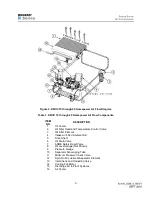
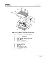
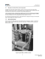
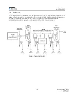
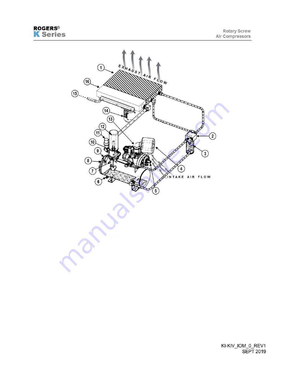
Figure 2. KI/KIV 10 through 20 Horsepower Air Flow Diagram.
Table 1. KI/KIV 10 through 20 Horsepower Air Flow Components.
ITEM
NO.
DESCRIPTION
1
Oil Cooler
2
Oil Filter Head and Temperature Control Valve
3
Oil Filter Element
4
Intake Air Filter (Ambient Air)
5
Drive Shaft
6
Oil Drain Valve
7
ASME Safety Relief Valve
8
Oil Level Gauge (Not Shown)
9
Pressure Gauge
10
Separator Scavenging Tube
11
Minimum Pressure Check Valve
12
Spin-On Air Lubricant Separator Element
13
Inlet Check and Unloading Valve
14
Cooling Fan Motor
15
Discharge Air to Plant Systems
16
Air Cooler
Summary of Contents for KI Series
Page 1: ...1 Model __________________ Serial __________________ Rotary Screw Air Compressors...
Page 8: ...7 INTENTIONALLY BLANK...
Page 9: ...8 CHAPTER 1 GENERAL INFORMATION...
Page 19: ...10 CHAPTER 2 INSTALLATION INSTRUCTIONS...
Page 26: ...17 CHAPTER 3 ELECTRICAL INFORMATION...
Page 30: ...21 CHAPTER 4 COMPRESSOR LUBRICANT...
Page 39: ...30 INTENTIONALLY BLANK...
Page 40: ...31 CHAPTER 5 AIR INLET FILTER INFORMATION...
Page 43: ...34 INTENTIONALLY BLANK...
Page 44: ...35 CHAPTER 6 COMPRESSOR OPERATIONS...
Page 49: ...40 INTENTIONALLY BLANK...
Page 50: ...41 CHAPTER 7 TROUBLESHOOTING...
Page 57: ...48 CHAPTER 8 FORMS RECORDS AND ELECTRICAL SCHEMATICS...
Page 58: ...49...
Page 59: ...50...
Page 60: ...51...
Page 61: ...52...
Page 62: ...53...
Page 63: ...54...
Page 64: ...55...
Page 65: ...56 INTENTIONALLY BLANK...
Page 66: ...57...


