13.
2.5.2
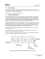
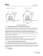
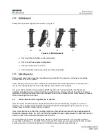
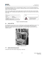
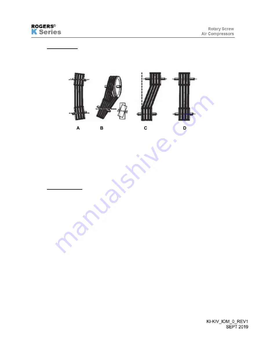
Belt Alignment
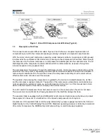
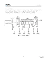
Examples of poor belt alignment are shown in Figure 2.
Figure 2. V-Belt Alignment.
a. Drive and driven shafts are not in alignment.
b. Driven shaft has angular misalignment.
c. Sheave locations are not inline.
d. Correct location of sheaves, belts are inline and parallel.
2.5.3
V-Belt Inspection
Remove belt guard and inspect belt condition during the 6,000 hour service or whenever conditions
indicate there may be a problem.
Check sheave grooves for nicks, scratches and wear. Belts should be inspected for unusual wear or
cracks. Thoroughly inspect the bore of the sheave and surface of the bushing.
Any paint, dirt, metal chips, fluid or grease MUST be removed. It is important to note that sheave
condition and alignment are vital to V-belt life and performance. Sheaves should be carefully checked
whenever V-belts are replaced. Mount the sheaves close to the compressor and motor housing to reduce
strain on bearings from side-load.
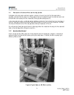
2.6
D-Face Mounted Drive System (60 to 100 HP)
Once the motor is bolted into the compressor’s D-Face mount at the factory, alignment is insured.
However, the coupling halves should be loosened and retracted during start up to insure the air end
rotates freely and motor rotation can be checked.
Once motor rotation is verified, the coupling halves may be pushed together with the coupling element
sandwiched between them. Do not force the hubs together or leave a gap between the hubs and element.
Simple contact of the hubs with the element is sufficient.
Do not operate the compressor without the element. Tighten the set screws on the coupling hubs to
secure them and the key to the shaft. The motor feet and compressor are supported by flexible vibration
isolating mounts to minimize transmission of vibration energy into the assembly base.
Summary of Contents for KI Series
Page 1: ...1 Model __________________ Serial __________________ Rotary Screw Air Compressors...
Page 8: ...7 INTENTIONALLY BLANK...
Page 9: ...8 CHAPTER 1 GENERAL INFORMATION...
Page 19: ...10 CHAPTER 2 INSTALLATION INSTRUCTIONS...
Page 26: ...17 CHAPTER 3 ELECTRICAL INFORMATION...
Page 30: ...21 CHAPTER 4 COMPRESSOR LUBRICANT...
Page 39: ...30 INTENTIONALLY BLANK...
Page 40: ...31 CHAPTER 5 AIR INLET FILTER INFORMATION...
Page 43: ...34 INTENTIONALLY BLANK...
Page 44: ...35 CHAPTER 6 COMPRESSOR OPERATIONS...
Page 49: ...40 INTENTIONALLY BLANK...
Page 50: ...41 CHAPTER 7 TROUBLESHOOTING...
Page 57: ...48 CHAPTER 8 FORMS RECORDS AND ELECTRICAL SCHEMATICS...
Page 58: ...49...
Page 59: ...50...
Page 60: ...51...
Page 61: ...52...
Page 62: ...53...
Page 63: ...54...
Page 64: ...55...
Page 65: ...56 INTENTIONALLY BLANK...
Page 66: ...57...


