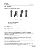
23.
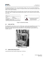
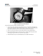
Check lubricant level in reservoir daily. Lubricant level must be checked with unit running at a consistent
pressure and loaded. The lubricant level should always be visible in the sight glass and never higher than
the run zone as indicated on the unit.
4.4
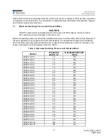
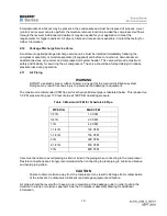
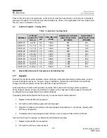
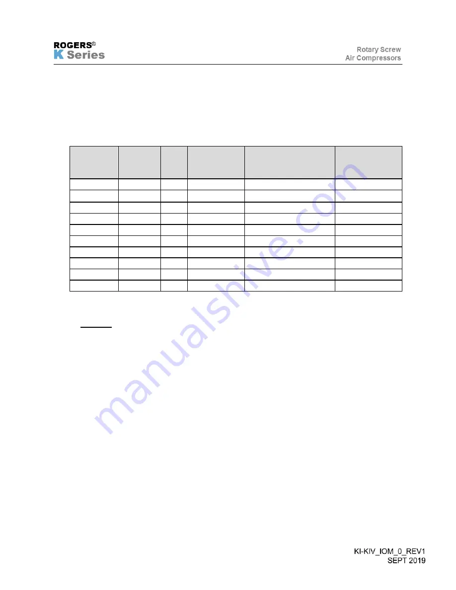
Lubricant System / Cooling Data
Table 1. Lubricant / Cooling Data.
4.5
Special Maintenance of Compressor Lubricant System
4.5.1 Deposits
Because the lubricant system operates under conditions of elevated temperature and pressure, solid or
semi-solid deposits may occur. However, proper installation, maintenance and filtration and lubricant
change intervals will greatly reduce the possibility of deposit formation.
Such deposits can interfere with operation of valves, filters and related cooling system equipment.
Minor deposits may be removed by flushing the system with an approved cleaning agent. Consult with
you Rogers factory representative for recommendations.
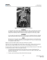
Completely drain lubricant while hot from every component that contains lubricant:
1. Replace lubricant filter and separator.
2. Fill machine with a factory-approved cleaning agent.
3. Operate the machine according to the cleaning agent manufacturer’s instructions, typically after
500 hours of operation.
4. Completely drain cleaning agent while hot from every component that contains lubricant.
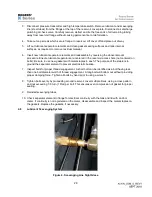
A second flush may be required, as determined with laboratory testing.
1. Replace lubricant filter and separator.
2. Fill machine with new, clean lubricant.
MODELS
SYSTEM
CAPACITY
GAL (L)
FAN
HP
COOLING AIR
(CFM)
LUBRICANT COOLER
HEAT REJECTION
(BTU/MIN)
BLOWDOWN
HEAT REJECTION
(BTU/MIN)
KI/KIV-10
2 (7.5)
0.5
1,800
351
88
KI/KIV-15
3 (11.3)
0.5
1,800
537
134
KI/KIV-20
3 (11.3)
0.5
1,800
792
198
KI/KIV-25
4.25 (16)
1.0
3,600
976
244
KI/KIV-30
4.25 (16)
1.0
3,600
1,209
302
KI/KIV-40
7.5 (28)
1.0
3,600
1,463
373
KI/KIV-50
7.5 (28)
1.0
3,600
1,775
444
KI/KIV-60
8 (28.3)
1.0
3,600
1,880
470
KI/KIV-75
10 (37.8)
1.5
5,500
2,603
651
KI/KIV-100
12 (45.4)
3.0
8,900
3,257
814
Summary of Contents for KI Series
Page 1: ...1 Model __________________ Serial __________________ Rotary Screw Air Compressors...
Page 8: ...7 INTENTIONALLY BLANK...
Page 9: ...8 CHAPTER 1 GENERAL INFORMATION...
Page 19: ...10 CHAPTER 2 INSTALLATION INSTRUCTIONS...
Page 26: ...17 CHAPTER 3 ELECTRICAL INFORMATION...
Page 30: ...21 CHAPTER 4 COMPRESSOR LUBRICANT...
Page 39: ...30 INTENTIONALLY BLANK...
Page 40: ...31 CHAPTER 5 AIR INLET FILTER INFORMATION...
Page 43: ...34 INTENTIONALLY BLANK...
Page 44: ...35 CHAPTER 6 COMPRESSOR OPERATIONS...
Page 49: ...40 INTENTIONALLY BLANK...
Page 50: ...41 CHAPTER 7 TROUBLESHOOTING...
Page 57: ...48 CHAPTER 8 FORMS RECORDS AND ELECTRICAL SCHEMATICS...
Page 58: ...49...
Page 59: ...50...
Page 60: ...51...
Page 61: ...52...
Page 62: ...53...
Page 63: ...54...
Page 64: ...55...
Page 65: ...56 INTENTIONALLY BLANK...
Page 66: ...57...


