8.
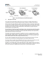
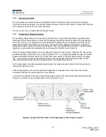
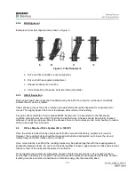
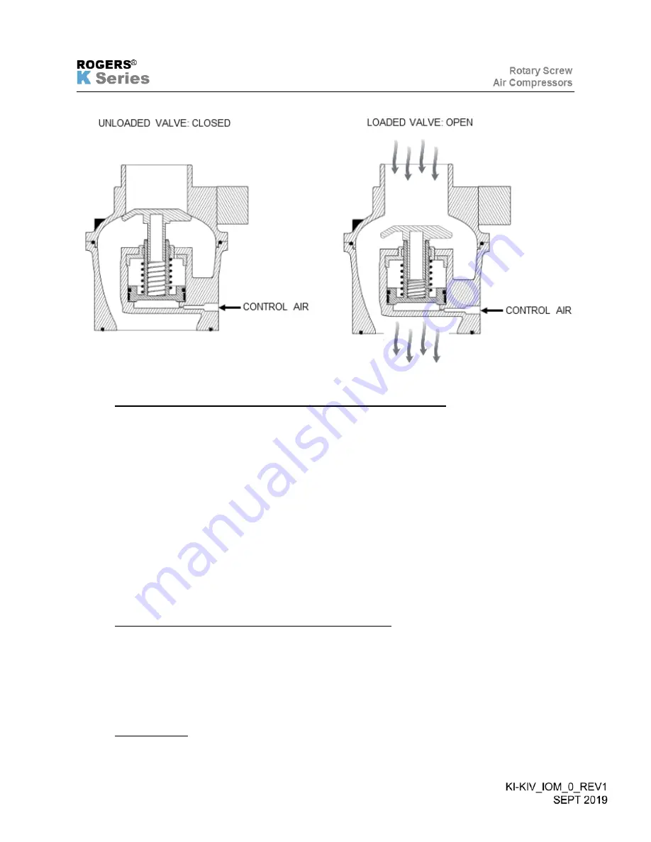
Figure 6. Typical Inlet Valve.
1.6.1
KI Series Standard Control, (10 – 100 HP), Load Unload Operation
The standard operating mode of the KI 10-100 HP unit is load / unload. The load and unload set points
are set in the controller and are adjustable (see Description of Operations / Display and Controls manual).
The operation of the inlet valve is controlled by the internal springs and control air. When control air
pressure is present the actuator / inlet valve piston moves and closes the inlet valve (unloads
compressor). When the control air signal is removed, the inlet valve opens, and the compressor is loaded.
When the compressor is unloaded, the control solenoid is de-energized and the control air valve is open,
allowing control air to close the inlet valve.
When the compressor is loaded, the control solenoid is energized and the control air valve is closed,
bleeding off the control air allowing the inlet valve to open.
The KI-100 also has a differential pilot and has the ability to control the compressor with upper end
modulation before unloading. See Description of Operations / Display and Controls manual.
1.6.2
KIV Series (10-100 HP), VFD Control and Load / Unload
The standard operating mode of the KIV-10 through 100 HP units is VFD speed control. The compressor
has a target set pressure which adjusts the speed of the motor and thus the compressor outlet flow.
The controller also has LOAD and UNLOAD PRESSURE SET POINTS which will unload the compressor
typically when the unit is at minimum speed. See Description of Operations / Display and Controls manual
for additional details.
1.6.3
Standby Delay
Summary of Contents for KI Series
Page 1: ...1 Model __________________ Serial __________________ Rotary Screw Air Compressors...
Page 8: ...7 INTENTIONALLY BLANK...
Page 9: ...8 CHAPTER 1 GENERAL INFORMATION...
Page 19: ...10 CHAPTER 2 INSTALLATION INSTRUCTIONS...
Page 26: ...17 CHAPTER 3 ELECTRICAL INFORMATION...
Page 30: ...21 CHAPTER 4 COMPRESSOR LUBRICANT...
Page 39: ...30 INTENTIONALLY BLANK...
Page 40: ...31 CHAPTER 5 AIR INLET FILTER INFORMATION...
Page 43: ...34 INTENTIONALLY BLANK...
Page 44: ...35 CHAPTER 6 COMPRESSOR OPERATIONS...
Page 49: ...40 INTENTIONALLY BLANK...
Page 50: ...41 CHAPTER 7 TROUBLESHOOTING...
Page 57: ...48 CHAPTER 8 FORMS RECORDS AND ELECTRICAL SCHEMATICS...
Page 58: ...49...
Page 59: ...50...
Page 60: ...51...
Page 61: ...52...
Page 62: ...53...
Page 63: ...54...
Page 64: ...55...
Page 65: ...56 INTENTIONALLY BLANK...
Page 66: ...57...


