

33.
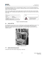
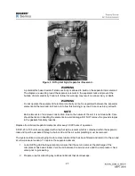
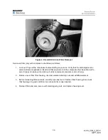
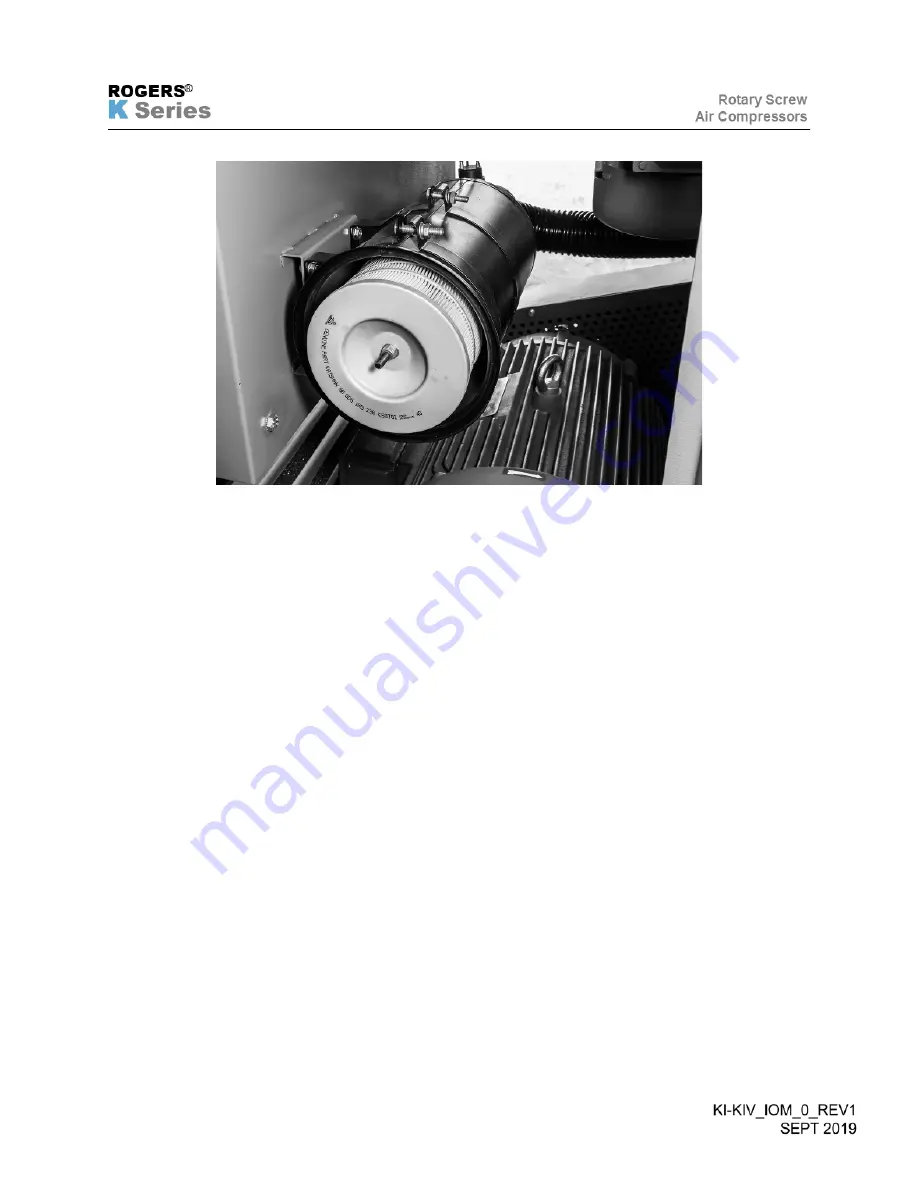
Figure 2. KI and KIV Air Inlet Filter Removal.
Service air filter (only with compressor shut down) as follows:
1. Lock out / Tag out the compressor before starting any service. Verify that the discharge service
valve (customer supplied) is closed and that air pressure in the compressor has been drained to
zero (0) psig. An open vent or drain will verify compressor pressure is zero (0) psig.
2. Remove cover from filter housing, unscrew element retaining nuts and withdraw element.
3. Before reinserting filter elements, carefully wipe dust out of inside of filter housing. Also check
that housing is in good condition (no serious dents or open seams).
4. Reinsert filter elements, secure with retaining wing nuts, and replace housing cover.
Summary of Contents for KI Series
Page 1: ...1 Model __________________ Serial __________________ Rotary Screw Air Compressors...
Page 8: ...7 INTENTIONALLY BLANK...
Page 9: ...8 CHAPTER 1 GENERAL INFORMATION...
Page 19: ...10 CHAPTER 2 INSTALLATION INSTRUCTIONS...
Page 26: ...17 CHAPTER 3 ELECTRICAL INFORMATION...
Page 30: ...21 CHAPTER 4 COMPRESSOR LUBRICANT...
Page 39: ...30 INTENTIONALLY BLANK...
Page 40: ...31 CHAPTER 5 AIR INLET FILTER INFORMATION...
Page 43: ...34 INTENTIONALLY BLANK...
Page 44: ...35 CHAPTER 6 COMPRESSOR OPERATIONS...
Page 49: ...40 INTENTIONALLY BLANK...
Page 50: ...41 CHAPTER 7 TROUBLESHOOTING...
Page 57: ...48 CHAPTER 8 FORMS RECORDS AND ELECTRICAL SCHEMATICS...
Page 58: ...49...
Page 59: ...50...
Page 60: ...51...
Page 61: ...52...
Page 62: ...53...
Page 63: ...54...
Page 64: ...55...
Page 65: ...56 INTENTIONALLY BLANK...
Page 66: ...57...