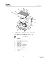
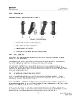
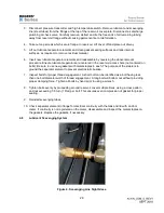

14.
Coupling element and hubs should be inspected during the 6,000 hour service or annually for wear and
replaced as necessary if corrosion, indentation, twisting or other deformation or degradation of materials
is noted.
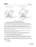
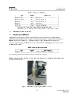
2.7
Cooling
Air compressors generate substantial quantities of waste heat. Careful consideration should be given to
the placement of the air compressor and the handling of the waste heat.
Install compressor so that there is no obstruction to air flow into and out of the cooler. Be especially
careful to avoid circumstances that allow hot air to re-circulate (such as near walls and ceilings),
inadequate room ventilation or placing the unit too close to other heat sources. See section 4.4 for cooling
data.
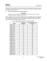
Maintain coolers free of dust, dirt, and foreign debris by choosing a location that minimizes exposure.
Ducting from discharge of air cooled coolers and require special design considerations to maintain
sufficient air flow for ventilation. Additional assist fan(s) may be necessary. Contact your Rogers factory
representative for assistance.
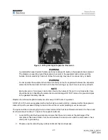
WARNING
Do not spray water on coolers during operation. Injury or death may result due to electrocution.
Damage to electrical components may also occur.
Lockout/Tagout the compressor when cleaning coolers. When cleaning is necessary, if possible, remove
shroud for best results. Vacuum or blow out large, loose debris.
For more extensive cleaning, protect electrical components such as the motor and starter and pressure
wash cooler cores from both sides, taking care to avoid damage to aluminum fins and fan blades. Wipe
all fan blades clean. Replace shroud. Ensure coolers are dry prior to returning to service.
Additional panel filters can be mounted on the exterior of the compressor cabinet to filter cooling air as it
enters the compressor cabinet. Contact your Rogers factory representative for assistance.
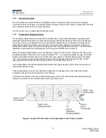
2.8
Blowdown
NOTE
Maintenance of the aftercooler is the same as the lubricant cooler and can be performed at
the same time.
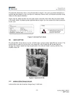
An aftercooler is installed between the combination minimum pressure / check valve and the compressor
package discharge. The aftercooler is mounted alongside of the lubricant cooler and utilizes the same
cooling fan for air flow. The aftercooler reduces the discharge air temperature often below the pressure
dewpoint temperature of the compressed air.
Condensation will occur is this situation and liquid moisture will need to be removed. An optional moisture
separator may have been purchased with your compressor to remove bulk moisture from the air stream.
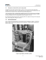
2.9
Optional Moisture Separator and Drain
An optional moisture separator and automatic drain may have been purchased with your air compressor.
If so, it should be mounted in the discharge piping shortly after leaving the compressor cabinet. The
moisture separator removes the condensed moisture by mechanical separation, gravity and centrifugal
action. The water is then expelled from the system to drain by a float type automatic drain.
Summary of Contents for KI Series
Page 1: ...1 Model __________________ Serial __________________ Rotary Screw Air Compressors...
Page 8: ...7 INTENTIONALLY BLANK...
Page 9: ...8 CHAPTER 1 GENERAL INFORMATION...
Page 19: ...10 CHAPTER 2 INSTALLATION INSTRUCTIONS...
Page 26: ...17 CHAPTER 3 ELECTRICAL INFORMATION...
Page 30: ...21 CHAPTER 4 COMPRESSOR LUBRICANT...
Page 39: ...30 INTENTIONALLY BLANK...
Page 40: ...31 CHAPTER 5 AIR INLET FILTER INFORMATION...
Page 43: ...34 INTENTIONALLY BLANK...
Page 44: ...35 CHAPTER 6 COMPRESSOR OPERATIONS...
Page 49: ...40 INTENTIONALLY BLANK...
Page 50: ...41 CHAPTER 7 TROUBLESHOOTING...
Page 57: ...48 CHAPTER 8 FORMS RECORDS AND ELECTRICAL SCHEMATICS...
Page 58: ...49...
Page 59: ...50...
Page 60: ...51...
Page 61: ...52...
Page 62: ...53...
Page 63: ...54...
Page 64: ...55...
Page 65: ...56 INTENTIONALLY BLANK...
Page 66: ...57...


