


11.
2.0
INSTALLATION
2.1
General
On receipt of unit, check for any damage received in transit. If damage or missing parts are noted, report
immediately to the delivering carrier. Care should be exercised when transporting the compressor to
avoid damage to the components.
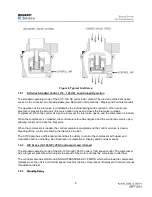
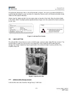
Check the compressor and motor base for support brackets which are painted red (see Chapter 6). These
brackets should be removed after installation. Their purpose is solely to prevent damage during transport.
NOTE
KI(V)-10 units do not have these shipping brackets.
2.2
Location
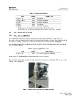
The unit should be installed in a clean, well ventilated area with adequate service clearance on all sides
of the machine. (Refer to the compressor assembly drawing) Select a location that will provide a clean,
cool, dry source of air for the inlet and compressor ventilation.
It may be necessary to install an outside source of clean air to the machine for cooling and for the inlet
air. The motor must not operate at full load for prolonged periods in ambient temperatures greater than
104 °F (40 °C). If ambient temperatures falls below 36 °F (2 °C), consult your Rogers factory
representative for recommendations on how to protect the machine from cold conditions.
Air-cooled units require large quantities of cooling air to remove the heat from compression. Obstruction
of the cooling air inlet and outlet areas of the compressor cabinet will negatively affect the reliability and
performance of the compressor.
Ideally the cooling air is ducted directly outside the compressor room rather than having the cooling air
discharged into the compressor room. Dilution cooling requires much higher volumes of cooling air to be
ventilated out of the compressor room.
2.3
Foundation
The air compressor unit does not require a heavy foundation. However, to maintain drive alignment and
prevent potentially damaging vibrations, the unit must be evenly supported. Mounting bolts, if used, must
be carefully secured such that the compressor base is not distorted. Do not weld on compressor unit or
base as damage to the bearings and or controls can occur. Do not use the wooden shipping pallet as a
permanent base.
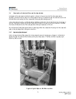
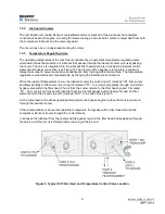
2.4
Compressor Rotation
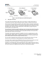
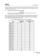
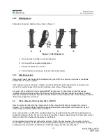
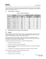
Rotary screw compressors require rotation in the correct direction to prevent damage to the bearings and
rotor clearances. It is critical that the rotation be established correctly during start up procedures and any
time that the motor leads or supply power phasing may have been changed. Examples include during
component replacement such as a motor, contactor or power supply components. Table 8 below states
the correct rotation for each model. The compressor casings are marked for correct rotation. It can be
noted that correct rotation will have the rotors separating from each other at the inlet.
Summary of Contents for KI Series
Page 1: ...1 Model __________________ Serial __________________ Rotary Screw Air Compressors...
Page 8: ...7 INTENTIONALLY BLANK...
Page 9: ...8 CHAPTER 1 GENERAL INFORMATION...
Page 19: ...10 CHAPTER 2 INSTALLATION INSTRUCTIONS...
Page 26: ...17 CHAPTER 3 ELECTRICAL INFORMATION...
Page 30: ...21 CHAPTER 4 COMPRESSOR LUBRICANT...
Page 39: ...30 INTENTIONALLY BLANK...
Page 40: ...31 CHAPTER 5 AIR INLET FILTER INFORMATION...
Page 43: ...34 INTENTIONALLY BLANK...
Page 44: ...35 CHAPTER 6 COMPRESSOR OPERATIONS...
Page 49: ...40 INTENTIONALLY BLANK...
Page 50: ...41 CHAPTER 7 TROUBLESHOOTING...
Page 57: ...48 CHAPTER 8 FORMS RECORDS AND ELECTRICAL SCHEMATICS...
Page 58: ...49...
Page 59: ...50...
Page 60: ...51...
Page 61: ...52...
Page 62: ...53...
Page 63: ...54...
Page 64: ...55...
Page 65: ...56 INTENTIONALLY BLANK...
Page 66: ...57...


