


4.
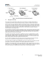
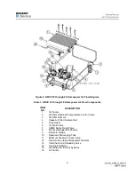
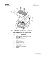
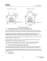
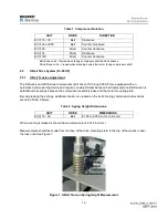
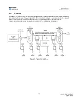
Figure 3. KI/KIV 25 through 100 Horsepower Air Flow Diagram.
Table 2. KI/KIV 25 through 100 Air Flow Components.
ITEM
NO.
DESCRIPTION
1
Oil Cooler
2
Oil Filter Head and Temperature Control Valve
3
Oil Filter Element
4
Intake Air Filter (Ambient Air)
5
Inlet Check and Unloading Valve
6
Drive Shaft
7
Oil Drain Valve
8
Oil Level Gauge (Not Shown)
9
ASME Safety Relief Valve
10
Oil Filler Port
11
Separator Scavenging Tube
12
Minimum Pressure Check Valve
13
Cooling Fan Motor
14
Discharge Air to Plant Systems
15
Air Cooler
Summary of Contents for KI Series
Page 1: ...1 Model __________________ Serial __________________ Rotary Screw Air Compressors...
Page 8: ...7 INTENTIONALLY BLANK...
Page 9: ...8 CHAPTER 1 GENERAL INFORMATION...
Page 19: ...10 CHAPTER 2 INSTALLATION INSTRUCTIONS...
Page 26: ...17 CHAPTER 3 ELECTRICAL INFORMATION...
Page 30: ...21 CHAPTER 4 COMPRESSOR LUBRICANT...
Page 39: ...30 INTENTIONALLY BLANK...
Page 40: ...31 CHAPTER 5 AIR INLET FILTER INFORMATION...
Page 43: ...34 INTENTIONALLY BLANK...
Page 44: ...35 CHAPTER 6 COMPRESSOR OPERATIONS...
Page 49: ...40 INTENTIONALLY BLANK...
Page 50: ...41 CHAPTER 7 TROUBLESHOOTING...
Page 57: ...48 CHAPTER 8 FORMS RECORDS AND ELECTRICAL SCHEMATICS...
Page 58: ...49...
Page 59: ...50...
Page 60: ...51...
Page 61: ...52...
Page 62: ...53...
Page 63: ...54...
Page 64: ...55...
Page 65: ...56 INTENTIONALLY BLANK...
Page 66: ...57...


