background image

SERVICE INSTRUCTION

CENTRIFUGAL COMPRESSORS

Supersedes: 160.49-M1 (1292)

Form 160.49-M1 (601)

USED WITH YORK MODEL YK

CENTRIFUGAL LIQUID CHILLERS
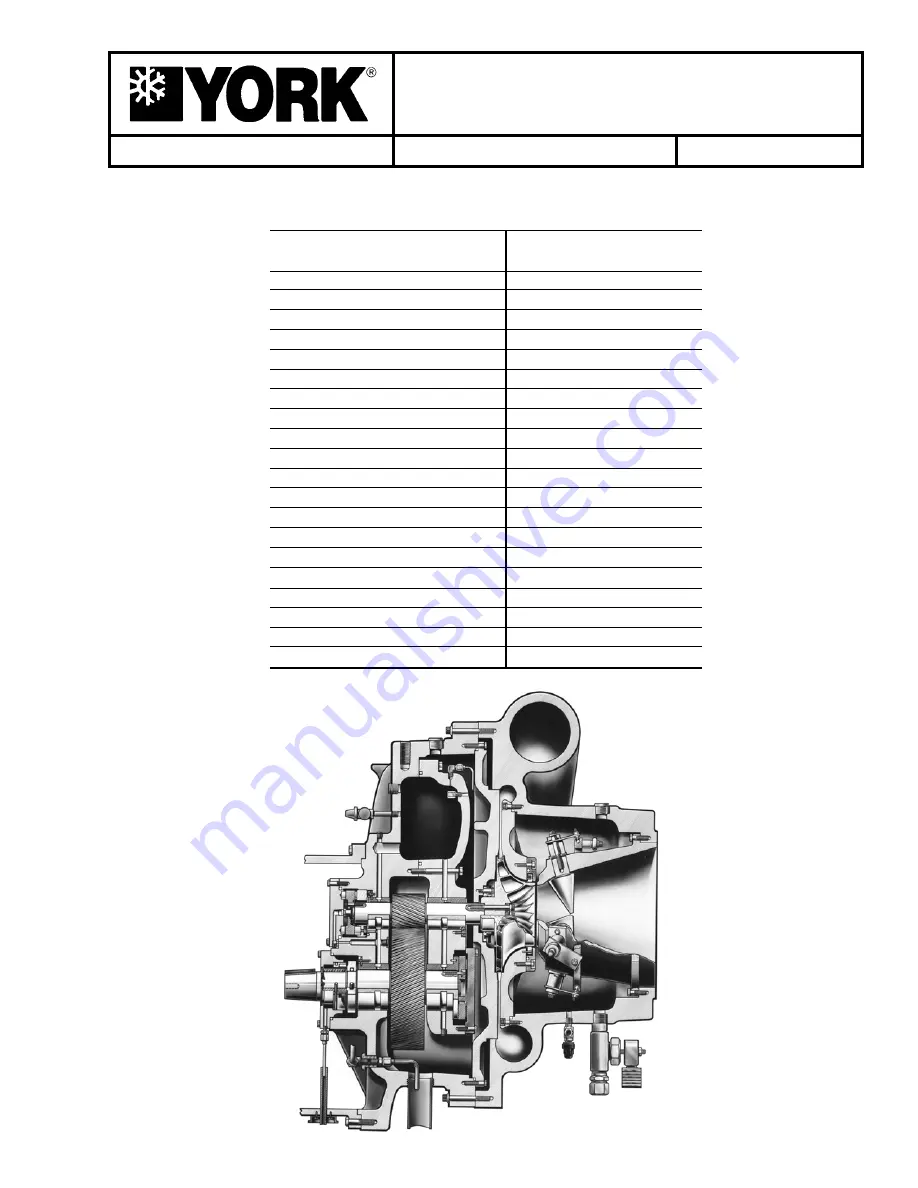
26439A

COMPRESSOR

COMPRESSOR

MODEL

CODE

YDHF-39

P1

YDHF-40

P2

YDHF-42

P3

YDHF-44

P4

YDHA-36 & LHA-36

G3

YDHA-41 & LHA-41

G4

YDHA-46 & LHA-46

H0

YDHA-50N & LHA-50N

H1

YDHA-50W & LHA-50W

H1

YDHB-57, LHB-57, HA-57

H2

YDHB-61

H3

YDHD-46

H4

YDHD-50N & 50W

H5

YDHD-57

H6

YDHD-59

H7

YDHD-61

H8

YDHA-65 & LHA-65

J1

YDHA-73 & LHA-73

J2

YDHA-81 & LHA-81

J3

YDHA-90 & LHA-90

J4

(Also see NOMENCLATURE, page 5)

Summary of Contents for YDHF-39

Page 1: ...R COMPRESSOR MODEL CODE YDHF 39 P1 YDHF 40 P2 YDHF 42 P3 YDHF 44 P4 YDHA 36 LHA 36 G3 YDHA 41 LHA 41 G4 YDHA 46 LHA 46 H0 YDHA 50N LHA 50N H1 YDHA 50W LHA 50W H1 YDHB 57 LHB 57 HA 57 H2 YDHB 61 H3 YDH...

Page 2: ...YORK INTERNATIONAL 2...

Page 3: ...s expected that this indi vidual possesses independent training that will enable them to perform their assigned tasks properly and safely It is essential that prior to performing any task on this equi...

Page 4: ...ing Bearing Housing 30 Installing Front High Speed Bearings 30 Installing Front Low Speed Bearings 30 Installing Balance Piston Diffuser Plate 31 Installing The Impeller 31 Disassembly Of Rotor Scroll...

Page 5: ...rnal and thrust bearings The open drive compressor shaft seal consists of a spring loaded precision carbon ring high temperature elastomer O ring static seal and a stress relieved precision lapped col...

Page 6: ...ce com pressor parts have been disassembled and cleaned many valuable indications of the compressor condition are lost Materials found in oil or on burned surfaces can often give an indication as to w...

Page 7: ...5CK 1700 CS 5CL 2635 CT 5CM 2635 CU 5CN 2635 CV 5CO 2635 CW 5CP 2930 CX 5CQ 2930 CY 5CR 2930 CZ 5CS 2930 CA 5CT 5750 CB 5CU 5750 DA 5CV 5750 D B 5CW 6800 DC 5CX 6800 5DA 7300 5DB 7300 HIGHVOLTAGE MOTO...

Page 8: ...R PLAIN 375 14 021 01262 4 HEX NUT 375 16 2 021 00467 5 GUIDE PIN 10 24 2 064 46488 6 EYE BOLT 3125 18 2 021 12420 7 WASHER PLAIN 3125 16 021 05166 8 GUIDE PIN 250 20 2 064 46499 9 HOOK TOOL 2 064 466...

Page 9: ...6 WASHER PLAIN 3 8 11 021 05167 17 EYE BOLT 5 16 2 021 12420 18 WASHER PLAIN 5 16 2 021 05166 19 PINION TOOL Mod 65 73 1 064 48028 20 PINION TOOL Mod 50 57 1 064 48029 21 PIPE 1 023 15508 ITEM DESCRIP...

Page 10: ...7 32 14 021 01276 4 NUT HEX HVY 1 2 2 021 02860 5 PIN GUIDE 2 064 46488 6 BOLT EYE 5 16 2 021 12420 7 WASHER PLAIN 11 32 16 021 05166 8 PIN GUIDE 1 4 20UNC 2 064 46499 ITEM DESCRIPTION QTY PART NO NO...

Page 11: ...4 48345 7 NUT HEX 4 021 00451 8 PIN GUIDE 2 064 46499 9 HOOK TOOL 2 064 46610 10 PIN GUIDE 3 8 3 064 18716 11 STUD SPECIAL 500 1 064 14500 ITEM DESCRIPTION QTY PART NO NO PER KIT 12 NUT HEX HVY 1 2 1...

Page 12: ...X 1 4 4 021 00451 8 PIN GUIDE 1 4 2 064 46499 9 HOOK TOOL 2 064 46610 10 PIN GUIDE 3 8 3 064 18716 ITEM DESCRIPTION QTY PART NO NO PER KIT 11 STUD SPECIAL 500 1 064 14500 12 NUT HEX HVY 1 2 1 021 0048...

Page 13: ...ement of these parts See Fig 17 Remove the coupling spool and disc packs 5 Taking care to see that the motor is properly sup ported remove the bolts that hold the motor to the motor adapter 6 Remove t...

Page 14: ...ferent designs Original design compressors used a car bon ring cartridge type shaft seal This design is shown in Figs 19 23 procedures for removal and installation are shown on pages 14 15 Beginning...

Page 15: ...s positioned with the lapped surface facing out See Fig 22 4 Re install the cover plate and seal cartridge assem bly Use care so that the carbon seal is not damaged 5 Re install the sleeve and secure...

Page 16: ...ow to remove and install these seals It is important that the shaft seal sleeve is securely attached to the com pressor shaft prior to removal of the retaining clips These clips protect the seal inter...

Page 17: ...he weight of the back end of the rotor support 4 Taking care that the motor is properly supported remove the bolts that hold the motor to the motor adaptor Remove the motor from the chiller and sit aw...

Page 18: ...SUPPORT ROTOR SCROLL 26439BA FIG 26 IMPELLER AND BALANCE PISTON IMPELLER SIZES 46 AND LARGER DIFFUSERPLATE BALANCE PISTON RETAINER SOCKET HEAD CAP SCREWS 3 IMPELLER CAP SCREWS 3 OR 6 IMPELLER CLAMPING...

Page 19: ...the following See Fig 27 Position compressor so that it is sitting on the correct horizontal plane to assure correct readings a Impeller rim Runout Design 0 003 Max b Impeller eye Runout Design 0 002...

Page 20: ...m tool kit into jacking holes and use proper rigging methods to lift diffuser plate from compressor Also remove o ring from back of dif fuser plate Original design balance piston seal on HA HB and HD...

Page 21: ...e Above BALANCE PISTON SEAL FIG 32 BALANCE PISTON SEAL 26344A DIFFUSER PLATE BALANCE PISTON SEAL BALANCE PISTON RETAINER HIGH SPEED SHAFT SOCKET HEAD CAP SCREWS SHOULDER BOLTS FIG 34 REMOVING DIFFUSER...

Page 22: ...peed bearing use 2 hook tools as shown in Fig 41 Carefully pull the bearing out of the bearing housing Note the position of roll pin See Fig 42 On the HF style compressors all low and high speed beari...

Page 23: ...837 FIG 41 FRONT LOW SPEED BEARING REMOVAL LD04836 FIG 43 FRONT HIGH SPEED BEARING REMOVAL FIG 44 ALL FRONT END BEARING REMOVED 26329A LOW SPEED BEARING LOW SPEED THRUSTBEARING INSIDE SURFACE 26332A F...

Page 24: ...low speed gear use a 1 2 13 eye bolt in the end of the shaft and pull the gear out of the rotor support Before re assembly be sure the compressor hous ing is absolutely clean by cleaning it with an ap...

Page 25: ...1 Inspect the bearing surface of the drive shaft and be sure the drive shaft is absolutely clean 2 Apply a light coat of oil and Molykote to the crank shaft and to the inside and outside surfaces of...

Page 26: ...ig 52 5 Remove the cap screws that hold the high speed thrust collar to the high speed shaft See Fig 53 Remove the thrust collar 1 4 20 puller holes are provided for convenience 6 Remove the high spee...

Page 27: ...UST COLLAR REMOVED 26339A HIGH SPEED FORWARD THRUST BEARING HIGH SPEED THRUST COLLAR INSIDE SURFACE PULLER HOLES 10 24 FORWARD THRUST BEARING 26338A FIG 54 HIGH SPEED FORWARD THRUST BEARING ROLL PIN H...

Page 28: ...oil and trip the pres sure switch to shut down the chiller 2 Remove the cap screws holding the high speed re verse thrust bearing and remove the bearing See Fig 50 Note alignment of oil passages 3 Bef...

Page 29: ...eed reverse thrust bearing Install re verse thrust bearing using a new o ring Be sure oil passages in the bearing line up with the oil passages in the compressor casing 7 Re install the Proximity Prob...

Page 30: ...speed bearing into place over the shaft and into the cavity in the bearing housing Install the retainer clip and cap screw INSTALLING FRONT LOW SPEED BEARINGS 1 Apply a coating of oil and Molykote to...

Page 31: ...e is 002 If T I R deviates from specification increase torque to 150 ft lbs Maximum to the bolts opposite to the high side Repeat as necessary until allowable T I R is achieved 7 Check high speed thru...

Page 32: ...ternal piping from the rotor scroll 4 Support the rotor scroll by proper rigging methods then remove the bolts holding the rotor scroll to the unit 5 Carefully remove the rotor scroll from the unit ba...

Page 33: ...on VaneAssembly can not be removed from the suction con nection side of the compressor on the HA HB and HD style compressors It must be removed from the inside of the rotor scroll housing AFTER the no...

Page 34: ...E ASSEMBLY OF THE EYE SEAL HA HB HD Style Compressors 1 Inspect all parts before re assembly See Clean ing and Checking Wearing Parts page 6 Re place with new parts as necessary 2 Be sure the helical...

Page 35: ...r on the HA HB and HD style compressors The rotor sup port must first be removed from the rotor scroll and the rotor scroll dissembled as described previously On the HF style compressor access to the...

Page 36: ...fully pull off the guide studs and place on a work bench to replace any parts 3 The PRV vanes are actuated by a rotating vane drive ring through individual vane arms to each vane Individual vanes may...

Page 37: ...ollowing parts are required To replace control shafts refer to Fig 63 and proceed as follows 1 Reduce the system pressure to slightly above at mospheric pressure 2 Disconnect the linkage from the exte...

Page 38: ...over plate cap screw to a torque of 35 ft lbs THIS IS IMPORTANT AND ASSURES THAT THE SLEEVE WILL TWIST EQUALLY WHEN THE VANES ARE MOVED TO EITHER THE WIDE OPEN OR THE FULLY CLOSED POSITION 19 Connect...

Page 39: ...aft with refrigerant oil Posi tion housing in place over the motor shaft and against the motor housing The pump housing match mark must be on one side of the motor Line the pump housing screw holes up...

Page 40: ...200 LD05199 ITEM DESCRIPTION QTY NO 1 OIL PUMP WITH MOTOR 1 2 HEATER 1 3 SENSOR TEMP 1 4 VALVE RELIEF 1 5 VALVE STOPANGLE 3 8 2 6 BOX ELECTRICAL 1 7 COVER ELECTRICAL BOX 1 8 SIGHTGLASS 2 9 GASKET COVE...

Page 41: ...IVEN GEAR 1 6 DRIVE GEAR 1 7 SQUARE KEY 1 8 HEX HD CAP SCREW 4 9 MODEL NUMBER IDENTIFICATION 1 10 MOTOR 1 LD05203 FIG 77 REMOVING THE DRIVE GEAR INNER PUMP GEAR PULLER 10 24 UNC x 1 1 2 LG SCREW PULL...

Page 42: ...asket and the oil pump and sump cover assembly to oil sump using the 16 5 8 hex nuts Tighten nuts using the alternating tightening method Torque to 155 ft lbs 3 Reconnect all electrical leads to fusit...

Page 43: ...FORM 160 49 M1 43 YORK INTERNATIONAL NOTES 3...

Page 44: ...ennsylvaniaUSA17405 1592 Subject to change without notice Printed in USA Copyright by York International Corporation 2001 ALL RIGHTS RESERVED Form 160 49 M1 601 Supersedes 160 49 M1 1292 Tele 800 861...

Reviews: