background image

Rockwell Automation Publication D2-3518-4 - January 2020

87

Parameter Descriptions

Chapter 9

Sets the high limit for the speed reference after scaling is applied. 

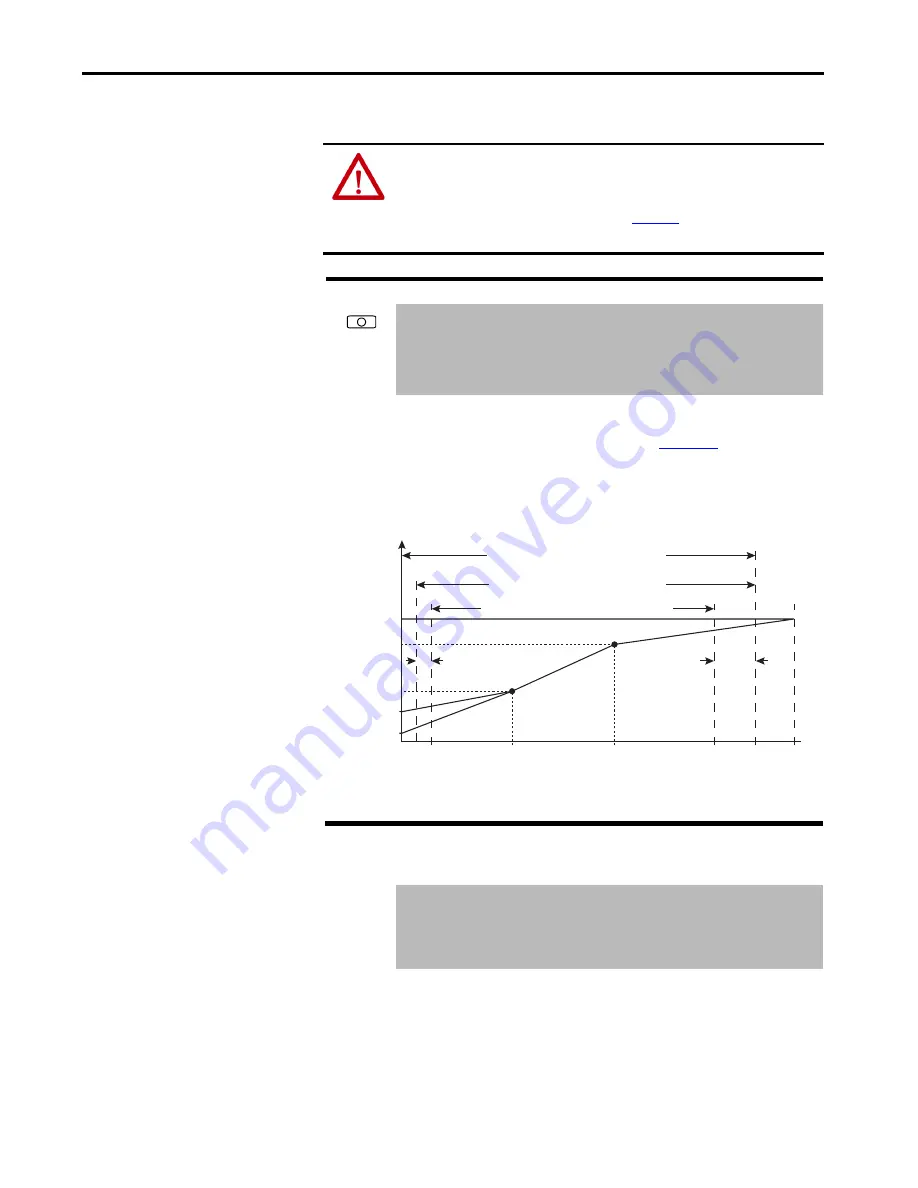
Sets the incremental amount of the output frequency (above Maximum Speed) 
allowable for functions such as slip compensation. See 

Figure 38

.

Maximum Speed + Overspeed Limit 

must be


≤ 

to Maximum Frequency.

Figure 38 - Speed Limits

Sets a frequency at which the drive will not operate (also called an 

avoidance 

frequency

). Requires that both Skip Frequency 1...3 and Skip Frequency Band 

(87) be set to a value other than 0.

ATTENTION: 

You are responsible for ensuring that driven machinery, all drive-

train mechanisms, and application material are capable of safe operation at the 
maximum operating speed of the drive. Overspeed detection in the drive 
determines when the drive shuts down. Se

Figure 38

Failure to observe this 

precaution could result in bodily injury.

83 

Overspeed Limit

Range:

0.0...20.0 Hz   [0.1 Hz]

Default:

10.0 Hz

Access:

1

Path:

 Speed Command > Spd Mode & Limits

See also:

55, 82

84
85
86 

Skip Frequency 1
Skip Frequency 2
Skip Frequency 3

Range:

-/+250.0   [0.1 Hz]

Default:

0.0 Hz

Access:

1

Path:

 Speed Command > Spd Mode & Limits

See also:

87

Allowable Output Frequency Range

Bus Regulation or Current Limit

V

o

l

t

a

g

e

Frequency

Allowable Output Frequency Range

Normal Operation

Allowable Reference Frequency Range

Frequency Trim due to

Speed Control Mode

Max Volts

Motor Volts

Break Volts

Start Boost

Run

0

Min

Speed

Motor

Hz

Max

Speed

Output

Freq Limit

Max

Freq

Break

Frequency

Overspeed

Limit

Summary of Contents for Allen-Bradley LiquiFlo 2.0

Page 1: ...LiquiFlo 2 0 AC Drive User Manual OriginalInstructions ...

Page 2: ...information circuits equipment or software described in this manual Reproduction of the contents of this manual in whole or in part without written permission of Rockwell Automation Inc is prohibited Throughout this manual when necessary we use notes to make you aware of safety considerations Labels may also be on or inside the equipment to provide specific precautions WARNING Identifies informati...

Page 3: ...mmunication Ports 32 Optional Equipment 33 Chapter3 Planning the Installation General Requirements for the Installation Site 35 Wiring Requirements for the Drive 41 Stopping the Drive 42 Chapter4 Mounting The Power Module and Grounding the Drive Lifting and Mounting the Drive 45 Grounding the Drive 46 Lifting and Mounting the Power Module 47 Chapter5 Installing Input and Output Power Wiring Instal...

Page 4: ...ng the Drive 191 Determining Drive Status Using the Status LEDs 192 About Alarms 194 About Faults 197 Diagnostic Parameters 211 Common Symptoms and Corrective Actions 212 Replacement Parts 214 Board Replacement Firmware Setup Procedures 218 Troubleshooting the Drive Using the OIM 222 Checking the Power Modules with Input Power Off 225 AppendixA Technical Specifications Service Conditions 229 Envir...

Page 5: ...OIM Reference 239 Customizing the Process Display Screen 239 Customizing the Function Keys 239 Controlling the Drive From the OIM 242 AppendixC LiquiFlo 2 0 Drive Frame 3 Wiring Diagrams Frame 3 Wiring Diagrams 243 AppendixD LiquiFlo 2 0 Drive Frame 4 Wiring Diagrams Frame 4 Wiring Diagrams 251 Index 259 ...

Page 6: ...6 Rockwell Automation Publication D2 3518 4 January 2020 Table of Contents Notes ...

Page 7: ... Manual publication D2 3488 Provides information explaining the uses and interface ofVS Utilities and information to help you complete basic tasks such as installing the software and starting the application and finding instructions tocompletemoresophisticatedtasksusingthe online help Industrial AutomationWiring and Grounding Guidelines publication 1770 4 1 Provides general guidelines for installi...

Page 8: ...8 Rockwell Automation Publication D2 3518 4 January 2020 Preface Notes ...

Page 9: ...e with a voltmeter to ensure the DC bus capacitors are discharged before touching any internal components Failure to observe this precaution could result in severe bodily injury or loss of life ATTENTION The drive can operate at and maintain zero speed You are responsible for assuring safe conditions for operating personnel by providing suitable guards audible or visual alarms or other devices to ...

Page 10: ...tly installed in a drive ATTENTION The drive contains ESD Electrostatic Discharge sensitive parts and assemblies Static control precautions are required when you install test service or repair this assembly Component damage can result if ESD control procedures are not followed If you are not familiar with static control procedures seeGuardingAgainstElectrostaticDamage publication8000 4 5 2 or any ...

Page 11: ...eceded by inverter or rectifier for reference For example inverter PI Control 125 Getting Assistance from Rockwell Automation If you have any questions or problems with the products described in this instruction manual contact your local Rockwell Automation sales office For technical assistance call 1 888 926 6786 Option 1 Also see Rockwell Automation Support on the back cover of this user manual ...

Page 12: ...12 Rockwell Automation Publication D2 3518 4 January 2020 Chapter 1 Introduction Notes ...

Page 13: ...rive by Cabinet Assembly ID Number Made in USA by Rockwell Automation Input 440 480VAC 60HZ 3PH Output 480VAC 405A 0 250 Hz Type Enclosure TYPE 1 Short Circuit Rating 65kAIC ID NO Cab Assy 180264 A03 600 Cabinet Assy S N XXXXXXXXXX PWR Mod S N XXXXXXXXXXX PWR Mod M N LF200460AAR Mfg On XX XX XX Design Pressure 185 psig Coolant Type R134a OR Treated Water Max Ambient 40 C FrameCode Frame3 180264 3 ...

Page 14: ...ge Suppressor 2 Terminal Block 6 position 3 Precharge Resistors 3 4 Power Module Assembly 5 Power Module Nameplate 6 Fuse Block 30 A 600V Class CC 3 Line 7 Fuse Class CC 600V 1 A 8 Fuse Class CC 600V 20 A 9 Line Sync PC Board Assembly 10 Line Sync Board Cover 11 115V Fan 6 in diameter 2 12 Capacitor Guard Panel not shown 13 Capacitor Bank Assembly 14 Fuse Block 30 A 600V Class CC 15 Fuse Class CC ...

Page 15: ...l Automation Publication D2 3518 4 January 2020 15 About the Drive Chapter 2 Figure 2 Drive Components Frame 3 L2 L1 L3 L2 L1 L3 U V W 1 2 8 6 3 4 5 6 7 9 10 11 25 12 13 26 16 15 14 18 17 19 27 20 21 22 23 24 ...

Page 16: ...2 6 Cable Assembly 30 pin 0 050 in Pitch Flex Film 2 7 Wire Harness Assembly Power Supply Upper Gate 2 8 Inverter Power Interface Assembly 9 Wire Harness Assembly Power Supply Lower Gate 2 10 Insulation Sheet 2 11 Communications Interface Assembly 12 Rectifier Power Interface Assembly 13 Wire Harness Assembly Gate Driver 14 Wire Harness Assembly Current Feedback Device 15 Wire Harness Assembly Lin...

Page 17: ...Rockwell Automation Publication D2 3518 4 January 2020 17 About the Drive Chapter 2 Figure 3 Power Module Component Locations Door Open Frame 3 15 16 13 2 14 12 8 10 4 4 10 3 7 7 1 1 9 9 11 6 5 6 5 7 25 ...

Page 18: ...18 Rockwell Automation Publication D2 3518 4 January 2020 Chapter 2 About the Drive Figure 4 Power Module Component Locations Door Closed Frame 3 22 21 23 20 11 19 17 18 24 20 Optional Optional ...

Page 19: ...Inductor 3 AC Contactor 4 Power Module Assembly 5 Input Filter Capacitor Assembly 6 OIM 7 Fans 115V AC Inductor 4 8 Transformer 5 kVA 9 Fan 115V AC Contactor 10 Resistors 100 kOhms 50 W 11 Precharge Resistors 12 Relay Oil Pump Control Power Terminals 13 Fuse Class RK 5 600V 10 A 2 14 Fuse Class CC 600V 25 A 1 15 Fuse Class CC 600V 10 A 1 16 Fuse Class T 600V 300 A 3 17 Fuse Class CC 600V 20 A 3 18...

Page 20: ...0 Rockwell Automation Publication D2 3518 4 January 2020 Chapter 2 About the Drive Figure 5 Drive Components Frame 4 L1 L3 L2 4 12 20 21 18 21 15 14 13 6 7 5 8 1 2 10 16 19 3 9 11 17 22 L1 L2 L3 U V W 23 ...

Page 21: ... Fan 24V DC 4 Internal Fan 24V DC 5 Wire Harness Assembly Internal Fan 6 Wire Harness Assembly DC Power 7 Wire Harness Assembly DC Bus Resistors 8 Current Feedback Device 2000 A 9 Wire Harness Assembly Current Feedback Device Rectifier Side 10 Wire Harness Assembly Current Feedback Device Inverter Side 11 Wire Harness Assembly RTD Recitifier Side 12 Wire Harness Assembly RTD Inverter Side 13 Cable...

Page 22: ...22 Rockwell Automation Publication D2 3518 4 January 2020 Chapter 2 About the Drive 5 3 1 2 9 11 8 12 4 10 6X 9 6 2X 7 UNDER TOP COVER ...

Page 23: ...Rockwell Automation Publication D2 3518 4 January 2020 23 About the Drive Chapter 2 Figure 7 Power Module Component Locations Front Panel Removed Frame 4 18 13 16 17 14 15 2X Optional Optional ...

Page 24: ...Power KVA InputVoltage V Input Current 2 Amps 2 460 A withrefrigerant 405 A with water as coolant Output Current at 2 kHz 3 Amps 3 110 output current capability for one minute 150 output current capability for 5 sec 180264 A03 LF200460AAR NEMA 1 337 480 10 405 405 180264 A06 LF200608CCR 505 608 608 180580 A07 LF200900CCR 673 900 900 180580 A09 1 1 No overload rating for 180580 A09 100 output curre...

Page 25: ...erminal provides terminals for six digital outputs that are non user configurable terminals 5 16 and 27 32 The state of these six outputs can be changed by writing to inverter parameter Appl Digital Out 30 Digital output 1 is always connected to the shunt trip circuit do not use digital output 1 for anything else The digital output devices are form C relays capable of switching 250V AC at 8 A or 3...

Page 26: ...26 Rockwell Automation Publication D2 3518 4 January 2020 Chapter 2 About the Drive Figure 9 AC Line I O Board Frame 3 AC Line I OTerminal Block detail AC Line I O Board AC Line I O Terminal Block ...

Page 27: ...C at 8 A or 30V DC at 8 A Analog Inputs The standard I O board terminal block provides two user configurable terminals for analog inputs terminals 1 4 and 17 20 Configure the inputs using inverter parameters Anlg In Config through Analog In 2 Loss 320 327 Each analog input has two modes voltage sensing input senses 10 V 10 V and current sensing input senses 0 mA 20 mA Separate terminals on the sta...

Page 28: ... Sel 342 to select any one of 31 analog outputs Terminals 8 and 9 output 4 20 mA Terminals 6 and 7 output 0 10 V Figure 10 Standard I O Board Frame 3 1 1 1 2 24 VOLT AC DC 24 VOLT AC DC C78 C79 C80 C81 C82 C83 C77 R83 R77 A2 A3 R81 R75 C75 R82 R76 R84 R78 R85 R79 R86 R80 U24 R74 C71 U8 A4 Q3 U27 U28 U29 Q2 J3 A 1 Standard I OTerminal Block Detail Standard I O Board Standard I O Terminal Block ...

Page 29: ...5 10 8 7 9 12 11 TB1 DI6 DI24V DICOM2 DI8 DI7 DI2 DI24V DI24V DI5 DI4 DICOM1 DI3 DI24V DI1 GATEKILL GATEKILL DIGITAL OUTPUT 2 DO8NO DO8COM DO3NC DO8NC DO7NO DO7COM DO7NC DO6NO DO6COM DO6NC DO5NO DIGITAL OUTPUT 1 DO4COM DO5COM DO5NC DO4NO DO3NO DO4NC DO3COM DO1NO DO2COM DO2NO DO2NC DO1NC DO1COM DIGITAL INPUT 2 DIGITAL INPUT 1 12V 1 AO1 OUTPUT ANALOG AO3 6 AO4 8 AO4 7 AO2 AO3 5 4 AO2 3 2 INPUT ANALO...

Page 30: ...I O board also contains dedicated terminals for driving the shunt trip circuit Analog Inputs The combined I O board provides two user configurable analog inputs Configure the inputs using inverter parameters Anlg In Config through Analog In 2 Loss 320 327 Each analog input has two modes voltage sensing input senses 10 V 10 V and current sensing input senses 0 mA 20 mA Separate terminals on the sta...

Page 31: ...used for each mode The mode is selected via inverter parameter Anlg Out Config 340 In this parameter if the lowest bit is set to 1 then the analog output is in voltage mode if set to 0 it is in current mode The following table describes the correspondence between the mode of the user configurable analog output and the combined I O board terminals that should be used The combined I O board contains...

Page 32: ... always plugged into DPI port 3 Figure 12 DPI Communication Interface Board Frame 3 For Frame 4 drives there is only one DPI port accessible via the OIM connector on the front panel of the power module see Figure 13 An internal cable connects this connector to the DIN connector on the control board A device plugged directly into this connector uses DPI port 3 If there is a requirement that multipl...

Page 33: ...odel Number Instruction Manual Operator Interface Module OIM RE1LCD LiquiFlo 2 0 AC Drive User Manual publication D2 3518 See Using the OIM on page 231 OIM LCD Hand held Cable RECBL LCD N A OIM Door mount Bezel Kit REBZL N1 MD60 MD65 Door Mount NEMA 1 OIM Bezel Kit MDI Instruction Manual publication D2 3517 Serial Converter with VS Utilities Software RECOMM 232 VS Utilities Getting Results Manual ...

Page 34: ...34 Rockwell Automation Publication D2 3518 4 January 2020 Chapter 2 About the Drive Notes ...

Page 35: ...ower For every 91 4 m 300 ft above 1000 m 3300 ft derate the output current 1 Verify that the drive location meets the environmental conditions specified in Table 4 Floor mounted units should be attached to the floor with the C channel rails provided See Figure 14 and Figure 16 ATTENTION Only qualified electrical personnel familiar with the construction andoperationofthisequipmentandthehazardsinvo...

Page 36: ... Figure 16 Overall power module dimensions are identified in these figures Frame 3 power modules LF200460AAR and LF200608CCR in Figure 15 Frame 4 power modules LF200900CCRand LF201215CCR in Figure 17 Condition Specification Operating Temperature inside NEMA ULType 1 enclosure 0 55 C 1 32 131 F 1 With typical heat rise inside a cabinet 40 C 104 F ambient outside usually results in 55 C 131 F inside...

Page 37: ...Rockwell Automation Publication D2 3518 4 January 2020 37 Planning the Installation Chapter 3 Figure 14 Exterior Enclosure Dimensions 180264 A03 and 180264 A06 Frame 3 in mm ...

Page 38: ...38 Rockwell Automation Publication D2 3518 4 January 2020 Chapter 3 Planning the Installation Figure 15 Power Module Dimensions LF200460AAR and LF200608CCR Frame 3 in ...

Page 39: ...ary 2020 39 Planning the Installation Chapter 3 Figure 16 Exterior Enclosure Dimensions 180580 A07 and 180580 A09 Frame 4 in 4 40 16 50 5 25 REF 1 000 21 47 26 43 26 43 21 47 1 000 0 63 TYP 0 50 TYP BOTTOM VIEW FILTER INSTALLED DRIVE PIPING ACCESS ...

Page 40: ...N G W A H C N I L A N I M R E T 3 M 2 1 A 2 6 5 8 2 2 1 O T 4 2 5 4 2 3 A 2 G N I T N U O M 3 M 6 5 5 4 R E B M U N L E D O M R E B M U N T R A P E M A R F R C C 5 1 2 1 0 2 F L 4 0 A 5 1 0 0 8 1 C C 4 SEE L I A T E D A W E I V T N O R F E D I S T F E L VIEW R E I F I T C E R E D I S R E T R E V N I E D I S 1 L 2 L 3 L 1 T U 2 T V 3 T W W O L F R I A Y T I V A R G F O R E T N E C 8 3 1 2 X 0 5 4 Y...

Page 41: ...ning Wire Size Requirements Determine wire size based on current requirements size of conduit openings and applicable local national and international codes for example NEC CEC regulations ConduitEntryOpeningSizes Determine the size of the conduit openings in the cabinet that the drive is mounted in so that the wire planned for a specific entry point will fit through the opening RecommendedPowerWi...

Page 42: ...ntrolled manner until the motor comes to a stop and then turns off the power devices You can also program zero speed with power maintained to the motor but in this condition the drive is not actually stopped In addition to the operational stop the LiquiFlo 2 0 power module provides a hardwired gate kill This function provides a two wire emergency stop circuit that does not depend on software or on...

Page 43: ... 2 DO8NO DO8COM DO3NC DO8NC DO7NO DO7COM DO7NC DO6NO DO6COM DO6NC DO5NO DIGITAL OUTPUT 1 DO4COM DO5COM DO5NC DO4NO DO3NO DO4NC DO3COM DO1NO DO2COM DO2NO DO2NC DO1NC DO1COM DIGITAL INPUT 2 DIGITAL INPUT 1 12V 1 AO1 OUTPUT ANALOG AO3 6 AO4 8 AO4 7 AO2 AO3 5 4 AO2 3 2 INPUT ANALOG ENCODER INPUT TB9 AO1 1 AI4 AI4 8 7 AI3 AI3 6 5 AI2 AI2 4 3 B TB8 AI1 AI1 2 1 B 6 A 3 A 5 4 COMMON 2 G1 1 TEMPSWRCT TEMPS...

Page 44: ...44 Rockwell Automation Publication D2 3518 4 January 2020 Chapter 3 Planning the Installation Notes ...

Page 45: ... careful to prevent damage due to dropping or jolting when moving the drive A forklift truck or similar means of lifting and transporting may be used Sling in a manner that equalizes the load at the lifting points Use a spreader bar if the angle of the sling is less than 45 degrees relative to horizontal Do not jolt while lifting Figure 19 Lift Point Locations for LiquiFlo 2 0 Drives Frame 3 Lifti...

Page 46: ...nclosure using 1 2 inch bolts grade 5 or better with compression washers Verify mounting bolt torque specifications Grounding the Drive Use the following steps to ground the drive 1 Open the door of the enclosure 2 Run a suitable equipment grounding conductor unbroken from the drive to earth ground Recommended tightening torque is 11 3 13 5 N m 100 120 lb in For Frame 3 see Figure 2 on page 15 for...

Page 47: ...rting may be used Sling in a manner that equalizes the load at the lifting points Use a spreader bar if the angle of the sling is less than 45 degrees relative to horizontal Do not jolt while lifting Figure 21 Lift Point Locations for LiquiFlo 2 0 Power Module Frame 3 Figure 22 Lift Point Locations for LiquiFlo 2 0 Power Module Frame 4 Lifting Hole both sides Lifting Hole both sides InputandOutput...

Page 48: ...ain 2 Use the hoist to carefully lift the power module from the horizontal shipping pallet 3 Position the power module in the prepared mounting location 4 Machine fasten the power module enclosure using 1 2 inch bolts grade 5 or better with compression washers Recommended tightening torque is 11 3 13 5 N m 100 120 lb in ATTENTION Do not use input and output busbars for lifting or handling Otherwis...

Page 49: ... the drive 2 Remove the input wiring panel and drill the required number of openings in the top of the drive enclosure Take care that metal chips do not enter the enclosure See Figure 14 on page 37 through Figure 17 on page 40 3 Wire the AC input power leads by routing them though the openings to the main input circuit breaker 4 Connect the three phase AC input power leads three wire 480V AC to th...

Page 50: ... output power motor leads to the power module busbars labeled U V and W See Figure 15 on page 38 and Figure 17 on page 40 4 Tighten the three phase AC output power terminals Frame 3 M10 Class 8 8 or 3 8 in Grade 5 fastener Tighten to 40N m 30 lb ft Frame 4 M12 Class 8 8 or 1 2 in Grade 5 fastener Tighten to 100N m 75 lb ft Table 5 Recommended Minimum Motor Lead Wire Size IMPORTANT The total motor ...

Page 51: ...circuit protection is installed and correctly rated ATTENTION Only qualified electrical personnel familiar with the construction and operation of this equipment and the hazards involved should start and adjust it Read and understand this manual in its entirety before proceeding Failure to observe this precaution could result in severe bodily injury or loss of life ATTENTION DCbuscapacitorsretainha...

Page 52: ... suitable earth ground is used Check for and eliminate any grounds between the motor frame and the motor power leads Verify that all ground leads are unbroken 12 Visually inspect the liquid cooling connections for leaks Powering Up After Installation Is Complete Use the following procedure to verify that the drive is installed correctly and is receiving the proper line voltage 1 Turn the input cir...

Page 53: ... with the operation of AC drives Be familiar with the operation of the OIM Have completed all hardware installation Properly connect the drive to the motor ATTENTION Only qualified electrical personnel familiar with the construction andoperationofthisequipmentandthehazardsinvolvedshouldinstall adjust operate or service this equipment Read and understand this chapter in its entirety before proceedi...

Page 54: ...matically advanced to the next step Exiting Before Completing the Start Up Routines To exit the Start up routines press the F4 key Exit When you select the Start up icon from the main menu again you are prompted to either continue or restart the Start up routines If you select Continue you are returned to the point at which you exited IMPORTANT Parametervaluesaresavedastheyarechanged Pressing orab...

Page 55: ...d list parameters allow a selection from two or more options The OIM displays a text message for each item Example inverter Speed Ref A Sel 90 Bit Parameters Bit parameters have individual bits associated with features or conditions If the bit is 0 the feature is off or the condition is false If the bit is 1 the feature is on or the condition is true Example inverter Drive Status 1 209 Numeric Par...

Page 56: ... Configuration Dynamic Control Internal Data Utility Communication Inputs and Outputs Each file contains parameters that are grouped by their function A file can contain several groups of parameters See Figure 25 Figure 25 Example of Parameter Organization Motor Control Motor Data Torq Attributes Motor Type Motor NP Volts Torque Perf Mode Maximum Voltage Volts per Hertz Start Acc Boost Run Boost S...

Page 57: ...Time 50 Motor NP Hertz 43 Motor OL Hertz 47 Torq Attributes Torque Perf Mode 53 Flux Up Mode 57 IRVoltage Drop 62 MaximumVoltage 54 Flux UpTime 58 Flux Current Ref 63 Maximum Freq 55 SV Boost Filter 59 IxoVoltage Drop 64 Compensation 56 Autotune 61 Volts per Hertz Start Acc Boost 69 BreakVoltage 71 Run Boost 70 Break Frequency 72 Speed Command Spd Mode Limits Speed Mode 80 Overspeed Limit 83 Skip ...

Page 58: ... HIM Ref Config Save HIM Ref 192 Man Ref Preload 193 MOP Config Save MOP Ref 194 MOP Rate 195 Drive Memory Param Access Lvl 196 SaveTo User Set 199 Voltage Class 202 ResetTo Defalts 197 Reset Meters 200 Drive Checksum 203 Load Frm Usr Set 198 Language 201 Diagnostics Drive Status 1 209 Dig Out Status 217 Status 1 Fault 227 Drive Status 2 210 Invtr BaseTemp 218 Status 2 Fault 228 Drive Alarm 1 211 ...

Page 59: ... Out D 1 Link DWord 1 316 Data In B 2 Link BWord 2 303 Data Out A2 Link AWord 2 311 Data Out D 2 Link DWord 2 317 Data In C 1 Link CWord 1 304 Data Out B 1 Link BWord 1 312 Data In C 2 Link CWord 2 305 Data Out B 2 Link BWord 2 313 Inputs Outputs Analog Inputs Anlg In Config 320 Analog In 1 Lo 323 Analog In 2 Lo 326 Anlg In Sqr Root 321 Analog In 1 Loss 324 Analog In 2 Loss 327 Analog In 1 Hi 322 ...

Page 60: ... Imbalance Lmt 62 RideThrough Ena 64 V ImbalanceTime 61 I ImbalanceTime 63 RideThrough Sec 65 Dynamic Control Control and Status Rectifier Contrl 100 Rectifier Status 101 BusVoltage Vdc Optimize 102 Vdc Reference 103 Vdc Command 104 Load Limits Current Limit 105 Max MotorVolts 107 Base Motor Freq 109 Input Load Amps 106 Max Motor Freq 108 RegulatorTuning VML Ki 110 CML Ki 112 VML Reset Level 114 V...

Page 61: ...oint 2 Sel 236 Fault Amps S 222 FaultVolts Q 227 Testpoint 2 Data 237 Fault AmpsT 223 FaultVolts D 228 Fault Amps Q 224 Testpoint 1 Sel 234 Fault Queue Fault Config 238 FaultTo Invertr 241 Fault 1 Code Fault 4 Code 243 245 247 249 Fault Clear 240 Power Up Marker 242 Fault 1Time Fault 4Time 244 246 248 250 Communications In Data Links IOC RedirTime 300 Service 302 302 IOC Redir Max 301 Service 303 ...

Page 62: ...g the Parameters Using the OIM Viewing Rectifier or Inverter Parameters The OIM initially displays information about the inverter including inverter parameters To display rectifier parameters and other information about the rectifier switch the OIM to the Active Rectifier device See Figure 27 Stopped Auto P0 LiquiFlo 2 0 Parameters Changed Params P Numbers By Group File File 2 Name File 3 Name Fil...

Page 63: ... 64 and Rectifier Parameters Basic Access Level on page 64 for parameters available at the Basic level The active access level is displayed in Parameter Access Level 196 To select the parameter access level using the OIM select the Password icon from the main menu See Figure 28 Figure 28 Selecting the Parameter Access Level Highlight Password icon ESC PROG LiquiFlo 2 0 0 LCD OIM 1 P0 LiquiFlo 2 0 ...

Page 64: ...LmtVal 320 Anlg In Config 53 Torque Perf Mode 155 Stop Mode A 322 Analog In 1 Hi 54 MaximumVoltage 156 Stop Mode B 323 Analog In 1 Lo 55 Maximum Freq 157 DC Brake Lvl Sel 325 Analog In 2 Hi 61 Autotune 158 DC Brake Level 326 Analog In 2 Lo 81 Minimum Speed 159 DC BrakeTime 342 Analog Out1 Sel 82 Maximum Speed 161 Bus Reg Mode A 343 Analog Out1 Hi 90 Speed Ref A Sel 162 Bus Reg Mode B 344 Analog Ou...

Page 65: ...erld 127 Start MoveTime 226 FaultVoltsVdc 21 Rctfr I2T Overld 128 Delay After Move 227 FaultVolts Q 22 Line I Imbalance 129 AmbientTemp 228 FaultVoltsD 23 LineV Imbalance 150 Input Load Amps 234 Testpoint 1 Sel 26 Rated kW 151 Current Limit 235 Testpoint1 Data 27 RatedVolts 152 LifeKW H 236 Testpoint2 Sel 28 Rated Amps 153 LifeRunTime 237 Testpoint2 Data 29 Control SWVer 154 Life PowerTime 238 Fau...

Page 66: ...k symbol on the screen changes from to Figure 29 Setting theWrite protect Password When you enter the password you can adjust parameters until you select Logout or return to the process display screen which re activates the password See Monitoring the Drive Using the Process Display Screen on the OIM on page 238 for information about the process display screen ATTENTION It is your responsibility t...

Page 67: ...omes the password value for all password protected OIMs Each OIM cannot have a different password value For example if the write protect password has been set to 5555 for the local OIM someone using a remote OIM with no write protect password set can still program all of the parameters If the write protect password is then set to 6666 on the remote OIM you are required to enter 6666 on the local O...

Page 68: ...68 Rockwell Automation Publication D2 3518 4 January 2020 Chapter 8 Programming Basics Notes ...

Page 69: ...0 Parameter Number Unique number assigned to each parameter Parameter Name Unique name assigned to each parameter Range Predefined parameter limits or selections Note that a negative Hz value indicates reverse rotation Default Factory default setting Access Parameter access level 0 Basic reduced parameter set most commonly used 1 Advanced full parameter set Path Menu selections to reach specified ...

Page 70: ...e fundamental voltage component 1 Output Freq Range 400 0 Hz 0 1 Hz Default Read Only Access 0 Path Monitor Metering See also 2 Commanded Freq Range 400 0 Hz 0 1 Hz Default Read Only Access 0 Path Monitor Metering See also 3 Output Current Range 0 0 3276 7 A 0 1 A Default Read Only Access 0 Path Monitor Metering See also 4 Torque Current Range 1800 0 A 0 1 A Default Read Only Access 1 Path Monitor...

Page 71: ... the drive firmware 7 Output Power Range 0 2400 0 kW 0 1 kW Default Read Only Access 1 Path Monitor Metering See also 8 Output Powr Fctr Range 0 00 1 00 0 01 Default Read Only Access 1 Path Monitor Metering See also 9 Elapsed MWh Range 0 0 429 496 729 5 MWh 0 1 MWh Default Read Only Access 1 Path Monitor Metering See also 10 Elapsed Run Time Range 0 0 429 496 729 5 Hr 0 1 Hr Default Read Only Acce...

Page 72: ... that is present on this drive and is controlled by the inverter Analog In3 Value 18 is not usable on LiquiFlo 2 0 drives and is only provided for compatibility with other drive models Analog In3 Value 18 is present on Frame 3 drives only The analog value of motor ground current Ground current trip is at about 50 of drive rated current The RMS motor output current value as follows 13 DC Bus Memory...

Page 73: ...e drive output voltage class The drive rated RMS output current 25 Est Input Power Range 0 0 3000 0 0 1 kW Default Read Only Access 1 Path Monitor Metering See also 7 26 Rated kW Range 0 00 3000 00 kW 0 01 kW Default Read Only Access 1 Path Monitor Drive Data See also 27 RatedVolts Range 480V 0 1V AC Default Read Only Access 1 Path Monitor Drive Data See also 28 Rated Amps Range 0 0 6553 5 Amps 0 ...

Page 74: ...firmware version 2 x only The lower byte of this parameter controls the state of the shunt trip digital output and the six application controlled digital outputs on the Combined I O board The upper byte controls the operation of the rectifier when configured for manual operation 30 Appl Digital Out Range See Figure 30 and Figure 31 Default See Figure 30 and Figure 31 Access 1 Path Monitor Applicat...

Page 75: ... in effect when the drive powers up This parameter value is not stored in non volatile memory For frame 3 drives firmware version 1 x the user configurable analog output hardware is located on the optional Standard I O Board This parameter is not usable if the optional Standard I O Board is not present See Standard I O Board Description Frame 3 Only on page 27 for terminal block assignments 31 App...

Page 76: ...so 30 0 The precharge is closed and voltage regulation is enabled when the inverter is requested to start 1 The precharge is closed and voltage regulation is enabled when power is turned on 2 The closing of the precharge and enabling of voltage regulation is controlled by some other device writing into inverter Appl Digital Out 30 3 Rectifier consists of a diode bridge This mode is for engineering...

Page 77: ...erational state of the drive x x x 0 0 1 1 2 3 4 5 6 7 8 9 11 12 13 14 15 x Reserved Bit A C L i n e I O D i g O u t p u t 1 A C L i n e I O D i g O u t p u t 2 A C L i n e I O D i g O u t p u t 3 A C L i n e I O D i g O u t p u t 4 A C L i n e I O D i g O u t p u t 5 A C L i n e I O D i g O u t p u t 6 C l o s e P r e c h a r g e E n a b l e R e c t i fi e r R e s e t R e c i fi e r F a u l t I n v...

Page 78: ...u n n i n g R e c t i fi e r F a u l t e d R e c t i fi e r i n L i m i t R e c t i fi e r S y n c h r o n i z e d R e c t i fi e r P h a s e d A C B R e c t i fi e r a t V o l t a g e R e c t i fi e r R e g e n e r a t i n g F a u l t R e s e t E c h o Nibble 1 Nibble 2 Nibble 3 Nibble 4 R e c t i fi e r C a r r i e r S y n c B i t 0 I n d i c a t e s O K t o R u n S t a n d b y x 0 0 1 1 2 3 4 5 6 7 8 ...

Page 79: ...nd rated temperature Set to the motor nameplate rated RPM The motor nameplate RPM defines the rated speed when operating at motor nameplate base frequency rated current base voltage and rated temperature This is used to calculate slip 41 Motor NPVolts Range 0 0 to Drive RatedVolts 0 1V AC Default Based on DriveType Access 0 Path Motor Control Motor Data See also 42 Motor NP FLA Range 0 0 to Rated ...

Page 80: ... motor overload fault 48 to occur it must be enabled using inverter parameter Fault Config 1 238 The drive output current is visible in inverter parameter Output Current 3 The motor overload fault occurs under these conditions If the drive output motor current is 138 of Motor OL Amps the fault occurs at 1 5 seconds If the drive output motor current is greater than 138 of Motor OL Amps the fault oc...

Page 81: ...ce Limit 49 for longer than the time in inverter Imbalance Time 50 the drive faults with the Motor I Imbalance fault fault 37 Also sets the time delay in generating a Current Feedback Lost Fault fault 35 If this parameter is set to exactly 10 0 seconds then the Current Feedback Lost Fault does not occur Sets the method of motor torque production 49 Imbalance Limit Range 0 0 40 0 0 1 Default 10 0 A...

Page 82: ...0 0 Hz Access 0 Path Motor Control Torq Attributes See also 82 83 rectifier 108 56 Compensation Range See Figure 37 Default See Figure 37 Access 1 Path Motor Control Torq Attributes See also Allowable Output Frequency Range Bus Regulation or Current Limit V o l t a g e Frequency Allowable Output Frequency Range Normal Operation Allowable Reference Frequency Range Frequency Trim due to Speed Contro...

Page 83: ...bit is for engineering use only Manual 0 Flux is established for Flux Up Time 58 before acceleration Auto 1 Flux is established for a calculated time period based on motor nameplate data Flux Up Time 58 is not used Sets the amount of time the drive uses to try to achieve full motor stator flux When a start command is issued DC current at current limit level is used to build stator flux before acce...

Page 84: ...tiates a Static Tune followed by a rotational test for the best possible automatic setting of Flux Current Ref A start command is required following initiation of this setting The parameter returns to Ready 0 following the test at which time another start transition is required to operate the drive in normal mode Calculate 3 This setting uses motor nameplate data to automatically set IR Voltage Dr...

Page 85: ...meter This parameter should be left at its default value of 0 0V AC Sets the voltage boost level for starting and acceleration when Custom V Hz mode is selected in Torque Perf Mode 53 Sets the boost level for steady state or deceleration when Fan Pmp V Hz or Custom V Hz modes are selected in Torque Perf Mode 53 63 Flux Current Ref Range 0 00 to Drive Rated Amps 0 01 A Default Based on Drive Rating...

Page 86: ...See also 53 71 83 80 Speed Mode Range 0 Open Loop 1 Slip Comp 2 Process PI Default 0 Open Loop Access 1 Path Speed Command Spd Mode Limits See also 124 138 81 Minimum Speed Range 0 0 to Maximum Speed 0 1 Hz Default 0 0 Hz Access 0 Path Speed Command Spd Mode Limits See also 83 92 95 ATTENTION The drive can operate at and maintain zero speed You are responsible for assuring safe conditions for oper...

Page 87: ...plicationmaterialarecapableofsafe operationatthe maximum operating speed of the drive Overspeed detection in the drive determines when the drive shuts down See Figure 38 Failure to observe this precaution could result in bodily injury 83 Overspeed Limit Range 0 0 20 0 Hz 0 1 Hz Default 10 0 Hz Access 1 Path Speed Command Spd Mode Limits See also 55 82 84 85 86 Skip Frequency 1 Skip Frequency 2 Ski...

Page 88: ...d 4 15 Preset Spd 5 16 Preset Spd 6 17 Preset Spd 7 18 DPI Port 1 19 DPI Port 2 20 DPI Port 3 21 DPI Port 4 22 DPI Port 5 Default 17 Preset Spd 7 Access 0 Path Speed Command Speed References See also 2 91 93 101 107 117 120 192 194 213 272 273 361 366 ATTENTION Removing and replacing the OIM while the drive is running may cause an abrupt speed change if the OIM is the selected reference source The...

Page 89: ... 3 8 Reserved 9 MOP Level 10 Reserved 11 Preset Spd 1 12 Preset Spd 2 13 Preset Spd 3 14 Preset Spd 4 15 Preset Spd 5 16 Preset Spd 6 17 Preset Spd 7 18 DPI Port 1 19 DPI Port 2 20 DPI Port 3 21 DPI Port 4 22 DPI Port 5 Default 17 Preset Spd 7 Access 0 Path Speed Command Speed References See also 2 91 93 101 107 117 120 192 194 213 272 273 361 366 ATTENTION Removing and replacing the OIM while the...

Page 90: ...wer value of the TB Man Ref Sel selection when the source is an analog input 94 Speed Ref B Hi Range Maximum Speed 0 1 Hz Default Maximum Speed Access 0 Path Speed Command Speed References See also 82 95 Speed Ref B Lo Range Maximum Speed 0 1 Hz Default 0 0 Hz Access 0 Path Speed Command Speed References See also 81 96 TB Man Ref Sel Range 1 Analog In 1 2 Analog In 2 3 8 Reserved 9 MOP Level Defau...

Page 91: ...Speed Ref A Preset Spd 1 7 100 Jog Speed Range 0 to Maximum Speed 0 1 Hz Default 10 0 Hz Access 0 Path Speed Command Discrete Speeds See also 101 102 103 104 105 106 107 Preset Speed 1 Preset Speed 2 Preset Speed 3 Preset Speed 4 Preset Speed 5 Preset Speed 6 Preset Speed 7 Range Maximum Speed 0 1 Hz Default See Table 7 on page 92 Access 101 107 0 Path Speed Command Discrete Speeds See also 90 93 ...

Page 92: ...0 0 Hz 104 Preset Speed 4 30 0 Hz 105 Preset Speed 5 40 0 Hz 106 Preset Speed 6 50 0 Hz 107 Preset Speed 7 60 0 Hz 117 Trim In Select Range 1 Analog In 1 2 Analog In 2 3 8 Reserved 9 MOP Level 10 Reserved 11 Preset Spd 1 12 Preset Spd 2 13 Preset Spd 3 14 Preset Spd 4 15 Preset Spd 5 16 Preset Spd 6 17 Preset Spd 7 18 DPI Port 1 19 DPI Port 2 20 DPI Port 3 21 DPI Port 4 22 DPI Port 5 Default 2 Ana...

Page 93: ...allow the slip compensation regulator to control drive operation Speed Mode 80 must be set to 1 Slip Comp 119 Trim Hi Range Maximum Speed 0 1 Hz Default 60 0 Hz Access 1 Path Speed Command SpeedTrim See also 82 117 120 Trim Lo Range Maximum Speed 0 1 Hz Default 0 0 Hz Access 1 Path Speed Command SpeedTrim See also 117 121 Slip RPM FLA Range 0 0 1200 0 RPM Default Based on Motor NP RPM Access 1 Pat...

Page 94: ...rror signal Enabling this feature creates a decrease in output for an increasing error and an increase in output for a decreasing error Bit 2 Preload Mode Enabled Initializes the PI integrator to the commanded speed while the PI is disabled Disabled The PI integrator is loaded with the PI Pre load 133 while the PI is disabled 123 Slip RPM Meter Range 300 0 RPM Default Read Only Access 1 Path Speed...

Page 95: ... allows the drive to take a reference signal setpoint and an actual signal feedback and automatically adjust the speed of the drive to match the actual signal to the reference Proportional control P adjusts the output based on the size of the error larger error proportionally larger correction Integral control I adjusts the output based on the duration of the error The integral control by itself i...

Page 96: ... Control 125 Bit 0 PI Enable Enables disables the operation of the PI loop Bit 1 PI Hold Enabled The integrator for the outer control loop is held at the current level that is it will not increase Enabled The integrator for the outer PI control loop is allowed to increase Bit 2 PI Reset Enabled The integrator for the outer PI control loop is reset to zero Disabled The integrator for the outer PI c...

Page 97: ...e 0 PI Setpoint 1 Analog In 1 2 Analog In 2 3 8 Reserved 9 MOP Level 10 Master Ref 11 Preset Spd 1 12 Preset Spd 2 13 Preset Spd 3 14 Preset Spd 4 15 Preset Spd 5 16 Preset Spd 6 17 Preset Spd 7 18 DPI Port 1 19 DPI Port 2 20 DPI Port 3 21 DPI Port 4 22 DPI Port 5 Default 0 PI Setpoint Access 1 Path Speed Command Process PI See also 124 138 127 PI Setpoint Range 100 00 of Maximum ProcessValue 0 01...

Page 98: ...MOP Level 10 Master Ref 11 Preset Spd 1 12 Preset Spd 2 13 Preset Spd 3 14 Preset Spd 4 15 Preset Spd 5 16 Preset Spd 6 17 Preset Spd 7 18 DPI Port 1 19 DPI Port 2 20 DPI Port 3 21 DPI Port 4 22 DPI Port 5 Default 2 Analog In 2 Access 1 Path Speed Command ProcessPI See also 124 138 129 PI IntegralTime Range 0 00 100 00 sec 0 01 sec Default 2 00 sec Access 1 Path Speed Command Process PI See also 1...

Page 99: ...nput is configured for PI Hold and is turned on or the PI Hold bit is set in PI Control 125 Bit 2 PI Reset Is set to 1 to indicate when the PI Integrator is being reset to zero Bit 3 PI InLimit 132 PI Upper Limit Range Maximum Frequency 0 1 Hz Default Maximum Freq Access 1 Path Speed Command Process PI See also 124 138 133 PI Preload Range Maximum Frequency 0 1 Hz Default 0 0 Hz Access 1 Path Spee...

Page 100: ...ge The rate established is the result of the following equation Maximum Speed Accel Time Accel Rate 135 PI Ref Meter Range 100 00 0 01 Default Read Only Access 1 Path Speed Command Process PI See also 124 138 136 PI Fdback Meter Range 100 00 0 01 Default Read Only Access 1 Path Speed Command Process PI See also 124 138 137 PI Error Meter Range 100 00 0 01 Default Read Only Access 1 Path Speed Comm...

Page 101: ...added 1 2 at the beginning and 1 2 at the end of the ramp Selects the source for the adjustment of current limit i e parameter analog input etc Defines the RMS current limit value when Current Lmt Sel 147 Cur Lim Val 142 143 DecelTime 1 DecelTime 2 Range 0 1 100 0 sec 0 1 sec Default 10 0 sec Access 142 0 143 0 Path Dynamic Control Ramp Rates See also 142 143 146 361 366 146 S Curve Range 0 100 1 ...

Page 102: ...requency 151 to anything other than 4 kHz causes an immediate Carrier Sync Lost fault fault 247 149 Current Lmt Gain Range 0 5000 1 Default 200 Access 1 Path Dynamic Control Load Limits See also 147 148 150 Drive OL Mode Range 0 Disabled 1 Reduce CLim 2 Reduce PWM 3 Both PWM 1st Default 0 Disabled Access 1 Path Dynamic Control Load Limits See also 219 151 PWM Frequency Range 2 4 kHz 1 kHz Default ...

Page 103: ...llowed Failure to observe this precaution could result in bodily injury 157 DC Brake Lvl Sel Range 0 DC Brake Lvl 1 Analog In 1 2 Analog In 2 Default 0 DC Brake Lvl Access 0 Path Dynamic Control Stop Brake Modes See also 155 156 158 159 158 DC Brake Level Range 0 to Rated Amps x 1 5 0 1 A Default Rated Amps Access 0 Path Dynamic Control Stop Brake Modes See also 157 159 ATTENTION If a hazard of in...

Page 104: ... digital input to the terminal block If a dynamic brake resistor is connected to the drive Bus Reg Mode A and Bus Reg Mode B must be set to option 2 3 or 4 160 Bus Reg Ki Range 0 5000 1 Default 450 Access 1 Path Dynamic Control Stop Brake Modes See also 161 162 161 162 Bus Reg Mode A Bus Reg Mode B Range 0 Disabled 1 Adjust Freq 2 Dynamic Brak 3 Both DB 1st 4 Both Frq 1st Default Mode A 0 Disabled...

Page 105: ...ed reaches Max Speed Overspeed Limit Ifthisconditionisunacceptable actionshouldbetakento1 limitsupply voltages within the specification of the drive and 2 limit fast positive input voltage changes to less than 10 Without taking such actions if this operationisunacceptable theadjustfreqportionofthebusregulator function must be disabled see parameters 161 and 162 Actual deceleration times can be lon...

Page 106: ...Control Stop Brake Modes See also 168 Start At PowerUp Range 0 Disabled Default 0 Disabled Access 0 Path Dynamic Control Stop Restart Modes See also 169 Flying Start En Range 0 Disabled 1 Enabled Default 0 Disabled Access 1 Path Dynamic Control Stop Restart Modes See also 170 170 Flying Start Gain Range 20 32767 1 Default 4000 Access 1 Path Dynamic Control Restart Modes See also 169 174 Auto Rstrt...

Page 107: ... in Auto Rstrt Tries with less than 5 minutes between each fault the drive remains in the faulted state The fault Auto Rstrt Tries are logged in the fault queue The auto restart feature is disabled when the drive is stopping and during autotuning Note that a DC Hold state is considered stopping The following conditions abort the reset run process Issuing a stop command from any control source Note...

Page 108: ...the amount of time at or above Wake Level before a start command is issued This parameter is not used with LiquiFlo 2 0 AC drives 178 Sleep Wake Mode Range 0 Disabled Default 0 Disabled Access 1 Path Dynamic Control Restart Modes See also 179 Sleep Wake Ref Range 1 Analog In 1 2 Analog In 2 Default 2 Analog In 2 Access 1 Path Dynamic Control Restart Modes See also 180 Wake Level Range Sleep Level ...

Page 109: ...l Input or Decel Fault Rectifier can no longer synchronize to the AC line or DC bus voltage is 82 of its value at the time of the input power loss Continue Rectifier can no longer synchronize to the AC line or DC bus voltage is 305V DC 182 Sleep Level Range 4 000 mA 0 000V Wake Level 0 001 mA 0 001V Default 5 000 mA 5 000V Access 1 Path Dynamic Control Restart Modes See also 183 183 Sleep Time Ran...

Page 110: ...ing Start En parameter 169 If the motor is spinning in reverse at the time of the flying start sequence and inverter Direction Mode 190 is set to Reverse Disable then the flying start sequence is not able to match the speed of the motor and 0 Hz is used as the initial output frequency If the Power Loss Mode is set to Decel Decel Input or Decel Fault then the inverter handles power loss conditions ...

Page 111: ...iquiflo 2 0 drives this parameter should not be changed from its default and the digital inputs should not be configured to the Pwr Loss Lvl function Selects the source for control of drive direction 185 Power Loss Time Range 0 0 60 0 sec 0 1 sec Default 0 0 sec Access 0 Path Dynamic Control Power Loss See also 184 238 186 Power Loss Level Range 0 0 999 9 0 1V DC Default 0 0V DC Access 1 Path Dyna...

Page 112: ...rive receives unsigned reference 0 32767 and direction command separately from the DPI port For example the direction keys on an OIM apply the direction to the reference Bipolar Drive receives signed reference 32767 32767 In this case the direction keys have no effect Reverse Disable Drive receives signed reference 32767 32767 however regardless of the reference the drive is not permitted to rever...

Page 113: ...rmware Displays the present parameter access level See Selecting the Parameter Access Level on page 63 for more information about parameter access levels 194 Save MOP Ref Range See Figure 44 Default See Figure 44 Access 1 Path Utility MOP Config See also 195 MOP Rate Range 0 2 250 0 0 1 Hz sec Default 1 0 Hz sec Access 1 Path Utility MOP Config See also 196 Param Access Lvl Range 0 Basic 1 Advance...

Page 114: ... After a Load From User Set operation is performed the value of this parameter returns to 0 for Ready Saves the inverter parameter values in active drive memory to a user set in drive non volatile memory An F Key on the OIM can be configured for this function See Appendix B After a Save To User Set operation is performed the value of this parameter returns to 0 for Ready 197 Reset To Defalts Range...

Page 115: ...des a checksum value that indicates whether or not a change in inverter configuration has occurred data values only 200 Reset Meters Range 0 Ready 1 MWh 2 ElapsedTime Default 0 Ready Access 1 Path Utility Drive Memory See also 201 Language Range 0 Not Selected 1 English 2 Francais 3 Espanol 4 Italiano 5 Deutsch 6 Reserved 7 Portugues 10 Dutch Default 0 Not Selected Access 0 Path Utility Drive Memo...

Page 116: ... 6 Auto Preset 7 Auto TB Manual Port 1 Manual Port 2 Manual Port 3 Manual Port 4 Manual Port 5 Manual Port 6 Manual 0 0 0 0 1 1 1 1 0 0 1 1 0 0 1 1 0 1 0 1 0 1 0 1 Port 0 TB Port 1 Port 2 Port 3 Port 4 Port 5 Port 6 No Local Control 210 Drive Status 2 Range See Figure 46 Default Read Only Access 1 Path Utility Diagnostics See also 209 0 1 1 0 0 0 0 1 0 1 1 1 0 0 0 0 0 0 1 1 2 3 4 5 6 7 8 9 11 12 1...

Page 117: ...ng bus frequency 211 Drive Alarm 1 Range See Figure 47 Default Read Only Access 1 Path Utility Diagnostics Utility Alarms See also 212 259 0 1 1 0 0 0 0 x 0 1 1 1 0 1 x x 0 0 1 1 2 3 4 5 6 7 8 9 11 12 13 14 15 1 ConditionTrue 0 Condition False x Reserved Bit R e a d y A c t i v e R u n n i n g J o g g i n g S t o p p i n g D C B r a k i n g A u t o T u n i n g A u t o R s t C t d n A u t o R s t A...

Page 118: ... Spd 3 14 Preset Spd 4 15 Preset Spd 5 16 Preset Spd 6 17 Preset Spd 7 18 DPI Port 1 19 DPI Port 2 20 DPI Port 3 21 DPI Port 4 22 DPI Port 5 23 DPI Port 6 Frame 4 only Default Read Only Access 1 Path Utility Diagnostics See also 90 93 96 101 214 Start Inhibits Range See Figure 49 Default Read Only Access 0 Path Utility Diagnostics See also 0 0 0 0 0 0 0 0 0 0 0 0 0 x x x 0 0 1 1 2 3 4 5 6 7 8 9 11...

Page 119: ...ame 4 Only on page 29 for a description of I O hardware that is present on this drive and is controlled by the inverter 215 Last Stop Source Range 0 Pwr Removed 1 DPI Port 1 2 DPI Port 2 3 DPI Port 3 4 DPI Port 4 5 DPI Port 5 6 DPI Port 6 Frame 4 only 7 Digital In 8 Fault 9 Not Enabled 10 Sleep 11 Jog Default Read Only Access 1 Path Utility Diagnostics See also 216 Dig In Status Range See Figure 5...

Page 120: ...ure 51 Dig Out Status 276 Frame 3 Frame 4 drives firmware version 2 x only Current state of the inverter controlled digital outputs Digital outputs 1 and 2 are the user configurable digital outputs Digital Outputs 3 8 are the application controlled digital outputs All of these digital outputs are located on the Combined I O board 217 Dig Out Status Range See Figure 51 and Figure 52 Default Read On...

Page 121: ...ore than inverter Imbalance Time 50 the Motor I Imbalance fault fault 37 occurs 218 Invtr BaseTemp Range 100 C 0 1 C Default Read Only Access 1 Path Utility Diagnostics See also 219 Drive OL Count Range 0 0 100 0 0 1 Default Read Only Access 1 Path Utility Diagnostics See also 150 220 Motor OL Count Range 0 0 100 0 1 0 Default Read Only Access 1 Path Utility Diagnostics See also 47 48 221 Imbalanc...

Page 122: ...mps at the time of the last fault Captures and displays the DC bus voltage of the drive at the time of the last fault Captures and displays Drive Status 1 bit pattern at the time of the last fault 224 Fault Frequency Range 400 0 Hz 0 1 Hz Default Read Only Access 1 Path Utility Diagnostics See also 225 230 225 Fault Amps Range 0 0 3276 7 A 0 1 A Default Read Only Access 1 Path Utility Diagnostics ...

Page 123: ...i n g A l a r m F a u l t e d A t S p e e d L o c a l I D 0 L o c a l I D 1 L o c a l I D 2 S p d R e f I D 0 S p d R e f I D 1 S p d R e f I D 2 S p d R e f I D 3 Nibble 1 Nibble 2 Nibble 3 Nibble 4 0 0 0 0 0 0 0 x 0 0 0 0 0 0 x x 0 0 1 1 2 3 4 5 6 7 8 9 11 12 13 14 15 1 Condition True 0 Condition False x Reserved Bit R e a d y A c t i v e R u n n i n g J o g g i n g S t o p p i n g D C B r a k i...

Page 124: ...ult Read Only Access 1 Path Utility Diagnostics See also 211 221 230 234 Testpoint 1 Sel Range 0 65535 1 Default 499 Access 1 Path Utility Diagnostics See also 235 235 Testpoint 1 Data Range 0 4 294 697 295 1 Default 0 Access 1 Path Utility Diagnostics See also 234 236 Testpoint 2 Sel Range 0 65535 1 Default 499 Access 1 Path Utility Diagnostics See also 237 0 0 0 0 0 0 0 0 0 0 0 0 0 x x x 0 0 1 1...

Page 125: ...4 294 967 295 1 Default 0 Access 1 Path Utility Diagnostics See also 236 238 Fault Config 1 Range See Figure 57 Default See Figure 57 Access 0 Path Utility Faults See also 240 Fault Clear Range 0 Ready 1 Clear Faults 2 Clr Flt Que Default 0 Ready Access 1 Path Utility Faults See also 241 Fault Clear Mode Range 0 Disabled 1 Enabled Default 1 Enabled Access 1 Path Utility Faults See also 32 1 x 1 1 ...

Page 126: ... the order they occur Fault 1 Code the most recent fault The time between initial power up and the occurrence of the associated fault Can be compared to Power Up Marker for the time from the most recent power up 242 Power Up Marker Range 0 0000 4 294 967 2925 Hr 0 0001 Hr Default Read Only Access 1 Path Utility Faults See also 244 246 248 250 252 254 256 258 243 245 247 249 251 253 255 257 Fault 1...

Page 127: ...ets all Alarm1 8 Code parameters 262 269 to zero 259 Alarm Config 1 Range See Figure 58 Default See Figure 58 Access 1 Path Utility Alarms See also 261 Alarm Clear Range 0 Ready 1 Clr Alarm Que Default 0 Ready Access 1 Path Utility Alarms See also 262 269 1 1 1 1 1 1 1 1 1 1 1 1 1 Enabled 0 Disabled x Reserved Bit Factory Default BitValues x x x x 0 0 1 1 2 3 4 5 6 7 8 9 11 12 13 14 15 P r e c h r...

Page 128: ...slt 271 262 263 264 265 266 267 268 269 Alarm 1 Code Alarm 2 Code Alarm 3 Code Alarm 4 Code Alarm 5 Code Alarm 6 Code Alarm 7 Code Alarm 8 Code Range 0 65535 Default Read Only Access 1 Path Utility Alarms See also 261 270 DPI Data Rate Range 0 125 kbps 1 500 kbps Default 1 Access 1 Path Communication Comm Control See also 271 Drive Logic Rslt Range See Figure 59 Default Read Only Access 1 Path Com...

Page 129: ...sk 276 Bits 1 Description 14 13 12 0 0 0 0 1 1 1 1 0 0 1 1 0 0 1 1 0 1 0 1 0 1 0 1 No Command Man Mode Ref A Auto Preset 2 Auto Preset 3 Auto Preset 4 Auto Preset 5 Auto Preset 6 Auto Preset 7 Auto 272 Drive Ref Rslt Range 32767 1 Default Read Only Access 1 Path Communication Comm Control See also 273 Drive Ramp Rslt Range 32767 1 Default Read Only Access 1 Path Communication Comm Control See also...

Page 130: ...ion Masks Owners See also 288 297 278 Jog Mask Range See Figure 61 Default See Figure 61 Access 1 Path Communication Masks Owners See also 288 297 279 Direction Mask Range See Jog Mask 278 Default See Jog Mask 278 Access 1 Path Communication Masks Owners See also 288 297 280 Reference Mask Range See Figure 62 Default See Figure 62 Access 1 Path Communication Masks Owners See also 288 297 0 0 0 0 0...

Page 131: ...0 Access 1 Path Communication Masks Owners See also 288 297 283 Fault Clr Mask Range See Reference Mask 280 Default See Reference Mask 280 Access 1 Path Communication Masks Owners See also 288 297 284 MOP Mask Range See Reference Mask 280 Default See Reference Mask 280 Access 1 Path Communication Masks Owners See also 288 297 285 Local Mask Range See Reference Mask 280 Default See Reference Mask 2...

Page 132: ... Range See Figure 63 Default Read Only Access 1 Path Communication Masks Owners See also 276 285 289 Start Owner Range See Stop Owner 288 Default Read Only Access 1 Path Communication Masks Owners See also 276 285 290 Jog Owner Range See Stop Owner 288 Default Read Only Access 1 Path Communication Masks Owners See also 276 285 291 Direction Owner Range See Stop Owner 288 Default Read Only Access 1...

Page 133: ...ee Stop Owner 288 Default Read Only Access 1 Path Communication Masks Owners See also 276 285 293 Accel Owner Range See Stop Owner 288 Default Read Only Access 1 Path Communication Masks Owners See also 276 285 294 Decel Owner Range See Stop Owner 288 Default Read Only Access 1 Path Communication Masks Owners See also 276 285 295 Fault Clr Owner Range See Stop Owner 288 Default Read Only Access 1 ...

Page 134: ...l for datalink information Parameter number whose value is written from a communications device data table Parameters that can be changed only while the drive is stopped cannot be used as Datalink inputs Entering a parameter of this type disables the link Refer to the appropriate communications option board manual for datalink information Parameter number whose value is written from a communicatio...

Page 135: ...e appropriate communications option board manual for datalink information Parameter number whose value is written to a communications device data table Parameter number whose value is written to a communications device data table 306 307 Data In D1 Link DWord 1 Data In D2 Link DWord 2 Range 0 387 1 Default 306 34 307 35 Access 1 Path Communication Datalinks See also IMPORTANT In Liquiflo 2 0 drive...

Page 136: ...ndication of the actual mode of the corresponding analog input if the input is physically present on the Combined I O board 314 315 Data Out C1 Link CWord 1 Data Out C2 Link CWord 2 Range 0 387 1 Default 0 Disabled Access 1 Path Communication Datalinks See also 316 317 Data Out D1 Link DWord 1 Data Out D2 Link DWord 2 Range 0 387 1 Default 316 33 317 218 Access 1 Path Communication Datalinks See a...

Page 137: ... the input and output ranges of the square root function are 0 10 volts Figure 65 Anlg in Sqr Root 321 The drive scales the value read from the user configurable analog input and converts it to units usable for the application You control the scaling by setting parameters that associate a low and high point in the input range with a low and high point in the target range Analog In 1 Hi sets the hi...

Page 138: ...onse when an analog signal loss is detected on user configurable analog input 1 Analog Input Scaling Example Assume Speed Ref A Sel Analog In 1 Minimum Freq 0 Hz Maximum Freq 60 Hz Analog In 1 Lo 0 0V Analog In 1 Hi 10 0V This is the default setting where minimum input 0V represents Minimum Speed and maximum input 10V represents Maximum Speed 323 Analog In 1 Lo Range 4 000 20 000 mA 0 001 mA 10 00...

Page 139: ... present on this drive and is controlled by the inverter ATTENTION Setting parameter 324 to a value greater than 1 allows the input signal to return to a usable level while the drive is running If a lost analog signal is restored while the drive is running the drive ramps to the restored reference level at the rate specified in AccelTime 1 140 AccelTime 2 141 DecelTime 1 142 and DecelTime 2 143 Be...

Page 140: ... for the input signal to return to a usable level while the drive is still running 327 Analog In 2 Loss Range 0 Disabled 1 Fault 2 Hold Input use last frequency command 3 Set Input Lo use Minimum Speed as frequency command 4 Set Input Hi use Maximum Speed as frequency command 5 Goto Preset1 use Preset1 as frequency command 6 Hold OutFreq maintain last output frequency Default 0 Disabled Access 1 P...

Page 141: ... Hi and Analog Out Lo parameters are an accurate indication of the actual mode of the analog output Selects whether the signed value or absolute value of a parameter is used before being scaled to drive the user configurable analog output See AC Line I O Board Description Frame 3 Only on page 25 through Combined I O Board Description Frame 4 Only on page 29 for a description of I O hardware that i...

Page 142: ...ion Frame 4 Only on page 29 for a description of I O hardware that is present on this drive and is controlled by the inverter 342 Analog Out1 Sel Range 0 Output Freq 1 Command Freq 2 Output Amps 3 Torque Amps 4 Flux Amps 5 Output Power 6 OutputVolts 7 DC BusVolts 8 PI Reference 9 PI Feedback 10 PI Error 11 PI Output 12 Motor OL 13 Drive OL 14 Application Default 14 Application Access 0 Path Inputs...

Page 143: ...n an analog output level corresponding to Analog Out1 Lo to 20 000 mA resulting in an analog output level corresponding to Analog Out1 Hi If Analog Out1 Sel 342 is set to Application 14 and the drive is a Frame 4 drive firmware version 2 x then the value entered in Appl Analog Out 31 is output directly on the analog output irrespective of the values of Analog Out1 Hi 343 and Analog Out1 Lo 344 Opt...

Page 144: ...eries Displays the measured temperature of the upper inverter IGBT power module in degrees C This parameter is only present on Frame 4 drives All such drives should have firmware version numbers in the 2 x series Displays the measured temperature of the lower inverter IGBT power module in degrees C 344 Analog Out1 Lo Range 4 000 20 000 mA 0 001 mA 10 000V 0 1V 0 0 10 000V 0 1V Default 4 0 mA Acces...

Page 145: ...sion numbers in the 2 x series Displays the measured ambient temperature of the drive in degrees C This parameter is only present on Frame 4 drives All such drives should have firmware version numbers in the 2 x series Displays the measured drive power supply temperature in degrees C This parameter is only present on Frame 4 drives All such drives should have firmware version numbers in the 2 x se...

Page 146: ...have firmware version numbers in the 2 x series Displays the measured voltage that identifies which type of Comblined I O board is installed This parameter is only present on Frame 4 drives All such drives should have firmware version numbers in the 2 x series 352 Inv PS 12 Range 3276 8V 3276 7V C Default Read Only Access 1 Path Inputs Outputs Temperature etc See also 353 Inv PS 12V Range 3276 8V ...

Page 147: ...cc2 Dec2 21 Accel 2 22 Decel 2 23 MOP Inc 24 MOP Dec 25 Excl Link 26 PI Enable 27 PI Hold 28 PI Reset 29 Pwr Loss Lvl 30 Precharge En 1 When Digital In x Sel is set to option 2 Clear Faults the stop key cannot be used to clear a fault condition 2 Typical 3 Wire Inputs These require that only 3 wire functions are chosen Including 2 wire selections causes a type 2 alarm 3 Typical 2 Wire Inputs These...

Page 148: ... input is open the drive will not start If the drive is already running when this input is opened the drive coasts and indicates not enabled on the OIM if present This is not considered a fault condition and no fault is generated If multiple enable inputs are configured the drive will not run if any of them are open 2 Clear Faults This function allows an external device to reset drive faults throu...

Page 149: ...ection control from the terminal block is enabled via the Logic Mask 276 and Direction Mask 279 A closed input sets the direction to reverse If the state of the input changes and the drive is running or jogging the drive changes direction If the Fwd Rev input function is assigned to more than one physical digital input at a time a digital input configuration alarm is asserted 7 Run An open to clos...

Page 150: ...pen 13 Stop Mode B This digital input selects between two different drive stop modes If the input is open then Stop Mode A selects which stop mode to use If the input is closed the Stop Mode B selects which stop mode to use If this input function is not configured then Stop Mode A selects which stop mode to use 14 Bus Regulation Mode B This digital input function selects how the drive regulates ex...

Page 151: ...n the parameter contains a frequency that is to be used as the reference The Speed Select input function configuration process involves assigning the functionality of the three possible Speed Select input functions to physical digital inputs The three Speed Select inputs functions are called Speed Select 1 Speed Select 2 and Speed Select 3 and they are assigned to physical inputs using the Digital...

Page 152: ... Accel Time 2 and another input function called Decel 2 selects between Decel Time 1 and Decel Time 2 The open state of the function selects Accel Time 1 or Decel Time 1 and the closed state selects Accel Time 2 or Decel Time 2 23 24 MOP Increment MOP Decrement The MOP is a reference setpoint called the MOP Value that can be incremented and decremented by external devices These input functions are...

Page 153: ...ction is open the integrator for the Process PI loop integrates normally 29 Pwr Loss Lvl Do not select the Pwr Loss Lvl input function in Liquiflo 2 0 drives 30 Precharg En This input function is used to manage disconnection from a common DC bus Do not select the Precharg En input function in Liquiflo 2 0 drives Type 2 Alarms Some digital input programming may cause conflicts that result in a Type...

Page 154: ...8 digital output 2 on the AC Line I O board is energized whenever the inverter is running even if an optional Standard I O board is not present 380 Digital Out1 Sel Range 1 Fault De energized Fault Energized No Fault 2 Alarm De energized Inverter Alarm Energized No Inverter Alarm 3 Ready 4 Run 5 Forward Run 6 Reverse Run 7 Auto Restart 8 Powerup Run 9 At Speed 10 At Freq 11 At Current 12 AtTorque ...

Page 155: ...ee AC Line I O Board Description Frame 3 Only on page 25 through Combined I O Board Description Frame 4 Only on page 29 for a description of I O hardware that is present on this drive and is controlled by the inverter Sets the off delay time for user configurable digital output 1 This is the time between the disappearance of a condition and de activation of the user configurable digital output See...

Page 156: ... Board Description Frame 4 Only on page 29 for a description of I O hardware that is present on this drive and is controlled by the inverter 384 Digital Out2 Sel Range 1 Fault De energized Fault Energized No Fault 2 Alarm De energized Inverter Alarm Energized No Inverter Alarm 3 Ready 4 Run 5 Forward Run 6 Reverse Run 7 Auto Restart 8 Powerup Run 9 At Speed 10 At Freq 11 At Current 12 AtTorque 13 ...

Page 157: ...digital output See AC Line I O Board Description Frame 3 Only on page 25 through Combined I O Board Description Frame 4 Only on page 29 for a description of I O hardware that is present on this drive and is controlled by the inverter Rectifier Parameters The input line frequency is displayed as x x Hz The RMS input phase current Ir is displayed as x x A 386 Dig Out2 OnTime Range 0 00 600 00 sec 0 ...

Page 158: ...ays be near 0 The RMS phase to phase input voltage Vrs is displayed as x x V 3 Input Current S Range 0 0 3276 7 A 0 1 A Default Read Only Access 0 Path Monitor Metering See also 4 Input Current T Range 0 0 3276 7 A 0 1 A Default Read Only Access 0 Path Monitor Metering See also 5 Active Current Range 3276 7 A 0 1 A Default Read Only Access 0 Path Monitor Metering See also 6 Reactive Current Range ...

Page 159: ...age is displayed as x x V DC 8 InputVoltage ST Range 0 0 3276 7V AC 0 1V AC Default Read Only Access 0 Path Monitor Metering See also 9 Input VoltageTR Range 0 0 3276 7V AC 0 1V AC Default Read Only Access 0 Path Monitor Metering See also 10 DC BusVoltage Range 0 0 3276 7V DC 0 1V DC Default Read Only Access 0 Path Monitor Metering See also 11 ActiveVoltage Range 0 0 3276 7V DC 0 1V DC Default Rea...

Page 160: ...is reset through the Reset Meters 200 parameter The elapsed run time is displayed as x x hours This parameter is reset through the Reset Meters 200 parameter 13 Input kW Range 2400 0 kW 0 1 kW Default Read Only Access 0 Path Monitor Metering See also 14 Input Pwr Factor Range 0 00 2 00 0 01 Default Read Only Access 0 Path Monitor Metering See also 15 Motoring kWh Range 0 0 429496729 5 kWh 0 1 kWh ...

Page 161: ...load fault fault 219 is generated The rectifier I2 T overload is displayed as x x where the value of 100 0 is the point where the rectifier I2T overload fault fault 220 is generated 18 Rctfr BaseTemp Range 20 0 120 0 C 0 1 C Default Read Only Access 0 Path Monitor Metering See also 19 Rctfr IGBTTemp Range 20 0 120 0 C 0 1 C Default Read Only Access 0 Path Monitor Metering See also 20 Rctfr IT Over...

Page 162: ... imbalance in volts is calculated as the larger of largest phase to phase voltage average phase to phase voltage or average phase to phase voltage smallest phase to phase voltage The imbalance in percent is calculated as Imbalance in volts average phase to phase voltage x 100 The rectifier rated kW is displayed as x xx kW 22 Line I Imbalance Range 0 0 100 0 0 1 Default Read Only Access 0 Path Moni...

Page 163: ...ne V Imbalance 23 is greater than V Imbalance Lmt 60 for this amount of time 27 RatedVolts Range 0 0 6553 5V AC 0 1V AC Default Read Only Access 0 Path Monitor Drive Data See also 28 Rated Amps Range 0 0 6553 5 A 0 1 A Default Read Only Access 0 Path Monitor Drive Data See also 29 Control SWVer Range x xxx Default Read Only Access 0 Path Monitor Drive Data See also 60 V Imbalance Lmt Range Path 0 ...

Page 164: ...e Thru Abort fault fault 221 occurs If the input power synchronization loss ends before the ride through timer expires the rectifier leaves Standby and re enters its normal running state The ride through timer of the rectifier expires when it reaches the value in Ride Through Sec 65 Note that the ride through timer of the rectifier is independent of the power loss timer of the inverter and that th...

Page 165: ...ration AC Line See also 64 inverter 184 185 100 Rectifier Contrl Range See Figure 68 and Figure 69 Default N A Access 0 Path Dynamic Control Control and Status See also inverter 33 IMPORTANT This parameter is used for communication between the inverter and the rectifier Do not write to this parameter usingVS Utilities DriveExplorer or an OIM Its value changes according to the operational state of ...

Page 166: ...perational state of the drive x 0 0 1 1 2 3 4 5 6 7 8 9 11 12 13 14 15 x Reserved Bit S h u n t T r i p Nibble 1 Nibble 2 Nibble 3 Nibble 4 x x x x x x x E n a b l e R e c t i fi e r C l o s e P r e c h a r g e R e s e t R e c t i fi e r F a u l t I n v e r t e r F a u l t N e t w o r k L o s s D C B u s L i m i t E x t e n d x x x x 0 0 1 1 2 3 4 5 6 7 8 9 11 12 13 14 15 x Reserved Bit O K t o R u ...

Page 167: ...tire drive is running is calculated based on a combination of the DC bus level necessary to provide the motor voltage required by the inverter and the measured line to line voltage of the AC line Vdc Reference 103 is not used in this case If Vdc Optimize 102 is set to Enabled the DC bus voltage required by the inverter is calculated from the output frequency of the inverter and the value of the Ma...

Page 168: ... measured by the rectifier visible in DC Bus Voltage 10 The maximum RMS current the rectifier produces expressed as x x A Sets the 100 current level for the rectifier I2T diagnostic Overload fault fault 220 103 Vdc Reference Range 400 0 800 0V DC x xV DC Default 700 0 Access 0 Dynamic Control BusVoltage See also 102 104 104 Vdc Command Range 400 0 800 0V DC x xV DC Default Read Only Access 0 Dynam...

Page 169: ...ual to Base Motor Freq 109 and from that point linearly varies the calculated motor voltage requirement down to 0 Volts at 0 Hz output frequency If the output frequency is greater than Base Motor Frequency 109 the calculated motor voltage requirement is limited to Max Motor Volts 107 If Vdc Optimize 102 is set to Enabled Max Motor Volts 107 should have the same value as inverter parameter Maximum ...

Page 170: ... inverter parameter Motor NP Hertz 43 Voltage Major Loop integral gain Voltage Major Loop proportional gain Current Minor Loop integral gain 109 Base Motor Freq Range 5 0 400 0 0 1 Hz Default 60 0 Access 0 Path Dynamic Control Load Limits See also 102 104 107 108 inverter 43 110 VML Ki Range 0 65535 Default Based on drive size Access 0 Path Dynamic Control RegulatorTuning See also 111 VML Kp Range...

Page 171: ...t measured rectifier IGBT module temperature is displayed as x x degrees C 113 CML Kp Range 0 65535 Default Based on drive size Access 0 Path Dynamic Control RegulatorTuning See also 114 VML Reset Level Range 10 0 300 0V DC 0 1V DC Default Based on drive size Access 0 Path Dynamic Control RegulatorTuning See also 120 Cold PlateTemp Range 20 0 120 0 C 0 1 C Default Read Only Access 0 Path Dynamic C...

Page 172: ...ct 123 124 125 126 127 128 CPC K1 CPC K2 HighTemp Limit LowTemp Limit Start Move Time Delay After Move Range 0 65535 Default 0 Access 0 Path Dynamic Control Cold Plate See also 129 AmbientTemp Range 20 0 120 0 C 0 1 C Default Read Only Access 0 Path Dynamic Control Cold Plate See also 120 121 122 150 Input Load Amps Range 0 0 100 0 Default Read Only Access 0 Path Internal Data Normalized Amps See ...

Page 173: ...rver message is received 153 Life RunTime Range 0 0000 to 429496 7295 hours Default Read Only Access 0 Path Internal Data Total Elapsed See also 154 Life PowerTime Range 0 0000 429496 7295 hours Default Read Only Access 0 Path Internal Data Total Elapsed See also 155 Life Power Cycle Range 0 4294967295 Default Read Only Access 0 Path Internal Data Total Elapsed See also 156 DPI Error Range 0 255 D...

Page 174: ... a DPI producer consumer message is transmitted 158 CS MsgTx Cnt Range 0 65535 Default Read Only Access 0 Path Internal Data DPI Counters See also 159 CSTimeout Cnt Range 0 255 Default Read Only Access 0 Path Internal Data DPI Counters See also 160 CS MSG Bad Cnt Range 0 255 Default Read Only Access 0 Path Internal Data DPI Counters See also 161 PC MSG Rx Cnt Range 0 65535 Default Read Only Access...

Page 175: ...vels 163 PCTimeout Cnt Range 0 255 Default Read Only Access 0 Path Internal Data DPI Counters See also 164 CAN Bus Off Cnt Range 0 65535 Default Read Only Access 0 Path Internal Data DPI Counters See also 171 172 173 174 D A Select N Range 0 65535 Default Read Only Access 0 Path Internal Data D A Output Sel See also 196 Param Access Lvl Range 0 Basic 1 Advanced Default 0 Access 0 Path Utility Driv...

Page 176: ...d data parameters After a Reset Meters operation is completed the value of this parameter reverts back to 0 for Ready This parameter is not used in the Liquiflo 2 0 rectifier 198 Load Frm Usr Set Range 0 3 Default Read Only Access 0 Path Utility Drive Memory See also 199 Save to User Set Range 0 3 Default Read Only Access 0 Path Utility Drive Memory See also 200 Reset Meters Range 0 Ready 1 MWh 2 ...

Page 177: ...ne I O Board Description Frame 3 Only on page 25 through Combined I O Board Description Frame 4 Only on page 29 for a description of I O hardware that is present on this drive and is controlled by the rectifier 211 Drive Alarm Range Default Read Only Access 0 Path Utility Status See also 214 Start Inhibits Range Default Read Only Access 0 Path Utility Status See also 216 Dig In Status Range Bits o...

Page 178: ...he AC line synchronization function of the AC Line I O board Bits 10 15 are for engineering use only On the Frame 3 drive AC Line I O Digital Inputs 3 and 4 are used to select measurements to be displayed on the optional input voltage and current meters as described in Table 13 Table 13 AC Line I O Digital Inputs 3 and 4 Frame 3 Dig In 4 Dig In 3 Selected Measurement 0 0 Iv Vst 0 1 Iw Vtr 1 0 Iu V...

Page 179: ...e I O Digital Inputs 3 and 4 Frame 4 Displays commanded status of the digital outputs that are controlled by the rectifier See AC Line I O Board Description Frame 3 Only on page 25 through Combined I O Board Description Frame 4 Only on page 29 for a description of I O hardware that is present on this drive and is controlled by the rectifier Dig In 2 Dig In 1 Selected Measurement 0 0 Iv Vst 0 1 Iw ...

Page 180: ...ectifier Contrl 100 is in addition to the internal rectifier conditions that can cause a shunt trip Frame 4 drives firmware version 2 x only Figure 75 Dig Out Status 217 Frame 4 On the Frame 4 drive the Combined I O Board dedicated Shunt Trip output is used to control the shunt trip and various conditions inside the drive can cause the shunt trip to be commanded A 1 in bit 0 of this parameter indi...

Page 181: ...Displays phase R RMS input current at the time of the most recent fault Displays phase S RMS input current at the time of the most recent fault Displays phase T RMS input current at the time of the most recent fault Displays active input current at the time of the most recent fault 220 Fault Frequency Range 400 0 Hz 0 1 Hz Default Read Only Access 0 Path Utility Diagnostics See also 221 Fault Amps...

Page 182: ...ecent fault This parameter is for service use only 225 Fault Amps D Range 0 0 3276 7 A 0 1 A Default Read Only Access 0 Path Utility Diagnostics See also 226 FaultVolts Vdc Range 0 0 3276 7V DC 0 1V DC Default Read Only Access 0 Path Utility Diagnostics See also 227 FaultVolts Q Range 0 0 3276 7V DC 0 1V DC Default Read Only Access 0 Path Utility Diagnostics See also 228 FaultVolts D Range 0 0 327...

Page 183: ...46 Default 0 Access 0 Path Utility Diagnostics See also 236 Testpoint 2 Sel Range 0 65535 Default 499 Access 0 Path Utility Diagnostics See also 237 Testpoint 2 Data Range 217483646 Default 0 Access 0 Path Utility Diagnostics See also 238 Fault Config Range See Figure 76 Default See Figure 76 Access 0 Path Utility Fault Queue See also 0 x x x x x x x x x x x x x x x 0 0 1 1 2 3 4 5 6 7 8 9 11 12 1...

Page 184: ...long with the rectifier fault timestamp parameters Fault n Time parameters below 244 246 248 250 to determine whether a rectifier fault in the rectifier fault queue happened before or after the most recent drive powerup This value rolls over to 0 after the drive has been powered on for more than the maximum value shown 240 Fault Clear Range 0 Ready 1 ClearFaults 2 ClearFlt Queue Default Read Only ...

Page 185: ... conditions to be reported as Input Current Imbalance faults fault 225 rather than as rectifier IOC faults rectifier faults 12 211 212 213 The purpose of this mechanism is to allow external drive control equipment to distinguish between faults caused by AC line events and faults caused by internal drive conditions A rectifier IOC condition is considered to be redirectable if it occurs more than 1 ...

Page 186: ...can occur before IOC fault redirection is disabled See rectifier parameter 300 for a description of the rectifier IOC fault redirect facility This parameter is for use by service personnel only This parameter is for use by service personnel only Displays the measured temperature of the top rectifier IGBT power module in degrees C 301 IOC Redir Max Range 0 30 Default 5 Access 0 Path Communications ...

Page 187: ...measured temperature of the bottom rectifier IGBT power module in degrees C This parameter is only present on Frame 4 drives All such drives should have firmware version numbers in the 2 x series Displays the measured rectifier coldplate temperature in degrees C This parameter is only usable if a coldplate temperature sensor is installed in the drive 346 Rct IGBTTmp Up Range 3276 8 3276 7 C Defaul...

Page 188: ...ch drives should have firmware version numbers in the 2 x series Displays the measured voltage of the 12V power supply This parameter is only present on Frame 4 drives All such drives should have firmware version numbers in the 2 x series Displays the measured voltage of the 12V power supply 350 Rct AmbientTmp Range 3276 8 3276 7 C Default Read Only Access 1 Path Inputs Outputs Temperature etc See...

Page 189: ...ld have firmware version numbers in the 2 x series Displays the measured voltage that identifies which type of IO board is installed This parameter is only present on Frame 4 drives All such drives should have firmware version numbers in the 2 x series 354 Rct I O IDV Range 3276 8 3276 7V C Default Read Only Access 1 Path Inputs Outputs Temperature etc See also ...

Page 190: ...190 Rockwell Automation Publication D2 3518 4 January 2020 Chapter 9 Parameter Descriptions Notes ...

Page 191: ...module 3 Verify that there is no voltage at the power module s input power terminals L1 L2 and L3 as shown in Figure 2 on page 15 for Frame 3 and Figure 5 on page 20 for Frame 4 4 Remove the cover of the power module ATTENTION Only qualified electrical personnel familiar with the construction andoperationofthisequipmentandthehazardsinvolvedshouldinstall adjust operate orservicethisequipment Readan...

Page 192: ...tifier sections each have a status LED For Frame 3 drives the status LEDs are located on the Communication Interface board and are labeled on the board itself as INV STATUS inverter and ACTIVE RECT STATUS rectifier See Figure 79 For Frame 4 drives the status LEDs are located on the Control Board and are labeled on the board itself as B2 inverter and B1 rectifier See Figure 80 DC Bus measurement po...

Page 193: ...LEDs Frame 3 Figure 80 Location of the Status LEDs Frame 4 DPI Communications Interface Board 12V INV LED D1 Inverter Status LED D3 Rectifier Status LED D4 12V RECT LED D2 Combined Control PCB RectifierStatus LED B1 Inverter Status LED B2 Frame 4 status LEDs are visiblethrough25mm 1in square cutout in front panel of power module ...

Page 194: ...esent Steady Rectifier running providing current to inverter Yellow Flashing Precharge contactor is open and rectifier is not running This is the normal state if the inverter is not running Steady A rectifier alarm condition exists rectifier may be running Check rectifier parameter 211 Alarm Status Red Flashing A rectifier fault has occurred This also causes an inverter fault and the fault is enun...

Page 195: ...alarm queue is separate from the inverter fault queue Alarm Descriptions Type Alarm Description User configurable These alarms alert the operator of conditions that if left untreated may lead to a fault condition The drive continues to operate during the alarm condition The alarms are enabled or disabled using inverter Alarm Config 1 259 The status of these alarms is shown in inverter Drive Alarm ...

Page 196: ...ter Overspeed Limit 83 exceeds inverter Maximum Freq 55 Raise inverter Maximum Freq 55 or lower inverter Maximum Speed 82 and or inverter Overspeed Limit 83 so that the sum is less than or equal to inverter Maximum Freq 55 MotorType Cflct InverterMotorType 90 hasbeensettoSyncPrmMagorSyncReluc andoneormoreDCfunctions forexample DC Boost DC Brake etc have been activated DC injection functions are in...

Page 197: ...g In ConflictB 2 UnderVoltage 19 Dig In ConflictC 3 Power Loss 20 Bipolar Conflict 5 Analog In Loss 21 MotorType Conflict 6 IntDBRes OvrHeat 22 NP Hz Conflict 8 Drive OL Level 1 23 MaxFreq Conflict 9 Drive OL Level 2 24 VHz Neg Slope 12 No Line Sync 25 IRVoltsRange 13 Power Phased ACB 26 FluxAmps Ref Rang 17 Dig In ConflictA 27 Speed Ref Cflct Type Fault Description Auto Reset Run If the drive is ...

Page 198: ...occur All entries in the fault queue are retained if power is lost The Time Stamp For each entry in the fault queue the system also displays a fault code and time stamp value The time stamp value is the value of an internal drive under power timer at the time of the fault The value of this timer is copied to PowerUp Marker 242 when the drive powers up The fault queue time stamp can then be compare...

Page 199: ...ulted status indication If any fault condition still exists the fault is latched and another entry made in the fault queue Note that performing a fault reset does not clear the fault queue Clearing the fault queue is a separate action See the Fault Clear 240 parameter description Fault Descriptions and Corrective Actions Frame3FaultDescriptionsandCorrectiveActions Table describes drive faults and ...

Page 200: ...tput rating it may be necessarytodisablethisfaultbysettinginverterImbalanceTime 50 to10 0 seconds 2 Verify connection of current feedback device and motor terminals 3 If fault repeats replace current feedback devices and or power supply Decel Inhibit 24 The drive is not following a commanded deceleration because it is attempting to limit bus voltage Enable disable with inverter Fault Config 1 238 ...

Page 201: ...mbalance 226 Rectifier LineV Imbalance 23 exceeded rectifier V Imbalance Lmt 60 for more than the time in rectifier V ImbalanceTime 61 1 Check for problem in input power distribution 2 Check line voltage feedback wiring and signal path includes line synchronization board AC Line I O board Rectifier control board Inv ShuntTrip 14 Drive has activated the shunt trip because the inverter firmware has ...

Page 202: ...ditions Busovervoltage can also be caused by motor regeneration Extend the decel time Parameter Chksum 100 The calculated checksum does not match the stored checksum for inverter parameter values read from non volatile memory on the inverter control board This fault can be cleared by writing a nonzero value to inverter ResetTo Defaults parameter 197 1 Restore inverter defaults using inverter Reset...

Page 203: ...meters 3 If fault still persists replace rectifier control board or rectifier power board Rctfr Dsat R S T 208 209 210 High current was detected in an IGBT 1 Check for loose connection in IGBT wire harness 2 Check IGBTs Rctfr Gnd Fault 216 Excessive input ground current measured Check for grounded input wiring Rctfr HW Unk 231 Rectifier portion of power structure hardware reported unexpected fault...

Page 204: ...power board was corrupted or could not be read from rectifier power board by rectifier firmware 1 Check connections between rectifier control board and rectifier power interface board If this fixes the issue then use rectifier ResetTo Defaults rectifier 197 to reset the rectifier to its defaults then reconfigure the drive as needed 2 Load updated drive rating information onto rectifier 3 Load upda...

Page 205: ...ion of current feedback device and motor terminals 3 If fault repeats replace current feedback devices and or power supply Decel Inhibit 24 Thedriveisnotfollowingacommandeddecelerationbecause it is attempting to limit bus voltage Enable disable with inverter Fault Config 1 238 1 Verify input voltage is within drive specified limits 2 Verify system ground impedance follows proper grounding techniqu...

Page 206: ...put power distribution 2 Check line voltage feedback wiring and signal path includes Combined I O board Combined Control board Inv ShuntTrip 14 Drive has activated the shunt trip because the inverter firmware has commanded it This can be caused by the detectionofamotor side inverter groundfault fault13 or by the user writing a 1 to bit 0 of inverter Appl Digital Out inverter 30 1 See table entry f...

Page 207: ...dvoltagewithinthe defined time 1 Verify that rectifier is currently synchronized to the AC line 2 Check all fuses and cabinet wiring 3 Replace I O board 4 Replace control board and or power board NTC Demux Fail 30 Control board cannot read temperature information from inverter half of power board 1 Clear faults 2 If fault persists verify connections to power board 3 If fault still persists replace...

Page 208: ...The checksum read from the Combined Power board inverter EEPROM does not match the checksum calculated from the EEPROM status data Clear the fault or cycle power to the drive Pwr Brd Chksum2 105 The checksum read from the Combined Power board inverter EEPROM does not match the checksum calculated from the EEPROM configuration data 1 Check connections between Combined Control board and Combined Pow...

Page 209: ...ne current increases Verify that such events have not occurred 4 Verify proper motor data is entered on inverter 5 Reduce rectifier current limit using rectifier Current Limit parameter 105 Rctfr OverVolt 224 The DC bus voltage is too high Monitor the AC line for high line voltage or transient conditions Bus overvoltage can also be caused by motor regeneration Extend the decel time Rctfr Pwr Board...

Page 210: ...p 8 Invtr BaseTemp 77 IRVolts Range 219 Rctfr IT Overld 9 Invtr IGBTTemp 78 FluxAmpsRef Rang 220 Rctfr I2T Overld 12 HW OverCurrent 79 Excessive Load 221 RideThru Abort 13 Ground Fault 80 AutoTune Aborted 222 High AC Line 14 Inv ShuntTrip 81 86 Port 1 6 DPI Loss 223 Low DC Bus 15 HiVdc Shunt 87 IXoVoltageRange 224 Rctfr OverVolt 18 Invtr I Offset U 100 Parameter Chksum 225 Input I Imbalance 19 Inv...

Page 211: ...r future use 2 Fault available on Frame 4 drives only 3 Fault available on Frame 3 drives only Table 23 Fault Names Cross Referenced by Fault Number No 1 Fault No 1 Fault No 1 Fault Diagnostic Parameter Number Value Displayed 1 DPI Error Status 2 Calculated IGBT JunctionTemperature 3 Active Current Limit 4 Active PWM Frequency 5 Lifetime MegaWatt Hours 1 1 Use the equation below to calculate total...

Page 212: ...ult and is not wired or is open Start or Run programming may be missing Program Digital Inx Sel 361 366 for correct inputs The Digital In bit of one or more of the mask parameters 276 285 is not set Set the Digital In bit to 1 in the appropriate mask parameters 276 285 The Digital In bit of the Logic Mask 276 must be setif any control function is tobe performed from the terminal block Flashing yel...

Page 213: ...expected Improper speed command Check for the proper speed command using steps 1 7 in tableTable 26 Programming is preventing the drive output from exceeding limiting values Incorrect programming Check Maximum Speed 82 and Maximum Freq 55 toinsure that speed is not limited by programming Indication Cause s Corrective Action None Motor data was incorrectly entered or autotune was not performed 1 Co...

Page 214: ...1T MISC B TR1 1 1 Fuse Holder 600V 30 A Buss R60030 2SR 1 1 Precharge Resistor 47 Ohm 300W 21T 322542 A02 set of 3 resistors 3 3 Resistor 100 kOhm 50W Dale RH 50 3 3 Circuit Breaker Main Qty 1 65kAIC base drive 1 100kAIC option O 21P CB A600 65 S 21P CB A600 100 S 100kAIC 21P CB A800 65 S 21P CB A800 100 S 100kAIC 21P CB A600 HDL Handle 1 O 1 1 O 1 Fuse Class RK 5 600V 15 A Gould Shawmut TRS R15 2...

Page 215: ...ly 21T 180090 A01 1 1 Inverter Control Assembly 21T 180064 A01 1 1 Connector Terminal Block 32 pin SK G9 TB1 S1 A 2 2 Internal Fan 21T 181775 A01 1 1 Rectifier Power Interface Assembly 440 A 2 300 A Modules 608 A 2 450 A Modules 21T 351839 A04 21T 351839 A05 1 1 Inverter Power Interface Assembly 460 A 2 300 A Modules 608 A 2 450 A Modules 21T 351893 A04 21T 351893 A05 1 1 Insulation Sheet 179700 2...

Page 216: ...2 Line 49454 19B 1 1 Lug 2 600 MCM Ground Thomas Betts ADR60 22D 1 1 115V Fan SK L1 FAN3 F3 4 4 Transformer 5 kVA Multi tap 21T MISC B TR1 1 1 Precharge Resistor 47 Ohm 300W 21T 322542 A02 set of 3 resistors 6 6 Circuit Breaker Main 1500 A Qty 1 65kAIC base drive 1 100kAIC option O 21T 380127 A03 21T 380127 A08 1 O 1 O Circuit Breaker Handle and Shaft 21T CB A1500 HDL 1 1 Fuse Class CC 600V 1 A Go...

Page 217: ... DC internal to power module 21T 181775 A02 1 1 Internal Fan 24V DC on bottom of power module 21T 181775 A03 2 2 Wire Harness Assembly Internal Fan 180316 Q01 1 1 Wire Harness Assembly Gate Driver Rectifier Side 180427 Q01 1 1 Wire Harness Assembly DC Power 180427 Q02 1 1 Current Feedback Device 1000 A 180307 Q01 1 1 Wire Harness Assembly DC Bus Resistors 180315 Q02 1 1 Current Feedback Device 200...

Page 218: ...d 0 2 If the fault still exists remove power to the entire drive wait 5 minutes and then restore power LiquiFlo 2 0 Frame 3 Firmware Setup Procedures InverterControlBoard 1 Reset all inverter parameters to defaults by setting inverter parameter 197 Reset to Defalts to 1 The value of parameter 197 Reset to Defalts returns to 0 immediately after 1 is written to memory This action should clear faults...

Page 219: ...eters RectifierControlBoard 1 Reset all rectifier parameters to defaults by setting rectifier parameter 197 Reset to Defalts to 1 The value of parameter 197 Reset to Defalts returns to 0 immediately after 1 is written to memory 2 If drive is still faulted attempt to reset the fault using the normal procedure See Clearing Drive Faults on page 218 If drive is still faulted after this attempt is made...

Page 220: ... after 1 is written to memory This action should clear faults 100 Parameter Checksum and 107 Replaced MCB PB 2 Reset all rectifier parameters to defaults by setting rectifier parameter 197 Reset to Defalts to 1 The value of parameter 197 Reset to Defalts returns to 0 immediately after 1 is written to memory 3 If drive is still faulted attempt to reset the fault using the normal procedure See Clear...

Page 221: ...er parameters to defaults by setting rectifier parameter 197 Reset to Defalts to 1 The value of parameter 197 Reset to Defalts returns to 0 immediately after 1 is written to memory 5 If drive is still faulted attempt to reset the fault using the normal procedure See Clearing Drive Faults on page 218 If drive is still faulted after this attempt is made troubleshoot on the basis of the current fault...

Page 222: ...matically retains a history of the last four faults that have occurred in the fault queue To access the fault queue press the F4 key at the process display screen or see Figure 82 to access the fault queue from the Main Menu Figure 82 Accessing the Fault Queue Figure 83 Sample Fault Queue Entry Diagnostics Device Version OIM Version View Fault Queue P0 LiquiFlo 2 0 Stopped Auto Main Menu Diagnosti...

Page 223: ... level Device Version on page 224 provides a general procedure for determining device version information for a device where the device is the inverter the rectifier or a DPI peripheral device To use this procedure first set the OIM to view information for the particular device See Viewing Rectifier or Inverter Parameters on page 62 for information on setting up the OIM so that it is displaying in...

Page 224: ...duct and Component Levels OIMVersion The OIM Version selection provides information on the OIM you are using to access this data See Figure 88 and Figure 89 Figure 88 Accessing the OIM Version Information Diagnostics OIM Version View Fault Queue Monitor Lang P0 LiquiFlo 2 0 Stopped Auto Main Menu Diagnostics Device Version Highlight Diagnostics icon Highlight item See figure below Diag Product Ver ...

Page 225: ...by a qualified person who understands the significance of setting them accurately Failure to observe this precaution could result in bodily injury Diag Prodct Ver Date mm dd yyyy FW Ver x xxx Series X Cmp F1 F1 Diag OIM Comp Prev LCD OIM Standard Control Board Prdt Next Flash To Component Level To Product Level F1 F3 Flash F W Information Diag Comp Ver FW Ver x xxx HW Ver xxx S xxxxxxxx Diagnostic...

Page 226: ... BusVolts power terminal Table 36 Output IGBT Components DC BusVolts power terminal DC BusVolts power terminal InputDiode No Meter Connection Component is OK if resistance R is Component is defective if 1 L1 10 R 1 megohm Continuity short circuit or open when the meter is connected with reversed polarity 2 L2 3 L3 4 L4 5 L5 6 L6 7 L1 8 L2 9 L3 10 L4 11 L5 12 L6 Output IBGT No Meter Connection Comp...

Page 227: ...he Drive Chapter 10 Contacting Technical Support for Assistance The Tech Support option in the Diagnostics menu provides information regarding technical support Also see Rockwell Automation Support on the back cover of this user manual for technical support contact information ...

Page 228: ...228 Rockwell Automation Publication D2 3518 4 January 2020 Chapter 10 Troubleshooting the Drive Notes ...

Page 229: ...ve Analog Speed Reference Resolution 1 4096 12 bits 0 025 Acceleration Adjustment Range 0 1 100 0 seconds within the ability of current Carrier Frequency 2 kHz 3 kHz or 4 kHz software selectable Current Limit Adjustment 25 150 of drive rated amps Service Factor 1 0 Speed Adjustable Range From 0 Hz to maximum speed Speed Regulation Motor slip dependent Speed Reference Resolution 0 01 with OIM 32767...

Page 230: ...Watts 18 000Watts 1 Coolant temperature must be above the dew point to preventcondensation If the water temperature is below the dew point the appropriate water flow rate control is needed Consult Rockwell Automation 2 WEG25 good quality or distilled water ethylene glycol 25 by volume An approved inhibited silicate free ethylene glycolis Ucartherm a product of Dow Chemical Company ATTENTION Ethyle...

Page 231: ...install the OIM on a Frame 3 Power Module connect the OIM to DPI port 3 on the DPI Communication Interface board until it clicks into place See Figure 92 To install the OIM on a Frame 4 Power Module connect the OIM to the OIM adapter on the lower right corner of the power module See Figure 93 To remove the OIM pull back on the OIM cable connector to release the OIM from the DPI Communication Inter...

Page 232: ...ary 2020 Appendix B Using the OIM Figure 92 Installing and Removing the Local OIM Frame 3 Figure 93 Installing and Removing the Local OIM Frame 4 tex t F1 ESC PROG HAND AUTO F2 F3 F4 o I DPI Communication Interface board DPI Port 3 OIM Connect OIM Here ...

Page 233: ...selected reference source but is not the selected control source The drive will ramp to the reference level provided by the OIM at the rate specified in AccelTime 1 140 AccelTime2 141 DecelTime1 142 andDecelTime2 143 Beawarethatan abrupt speed change may occur depending upon the new reference level and the rate specified in these parameters Failure to observe this precaution could result in bodily...

Page 234: ...reference control Stopthedrive ClearafaultiftheclearfaultsfunctionfortheOIMisenabledusingtheLogicMask 276 and Fault Clr Mask 283 Start the drive if start from the OIM is enabled via the Logic Mask 276 and Start Mask 277 F1 though F4 Predefined or user configured functions The definition of each key is shown directly above the key on the display See item in Figure 94 ATTENTION WhenswitchingfromAuto...

Page 235: ...et Reset Defaults Active User Set Language Function Keys Reset Display Display Video Display Timeout Monitor Device Identity Fast PwrUp Mode Contrast Set Wrt Prot PW Set Acc Lvl PW Set Access Lvl QuickStart Motor Data Configure I O Ref Setup Speed Limits Input Voltage Motor Tests Done ESC PROG Press Press Press to move between menu items to select a menu item to move 1 level back in the menu struct...

Page 236: ...from the Display menu Resetting the Display To return all the options for the display to factory default values select Reset Display from the Display menu Selecting a Device in the System The OIM can access and display data from any active drive or peripheral device on the network The drive port 0 is the default device selected To select a device select the Device Select icon from the Main Menu Th...

Page 237: ...hange Use to change the value of the bit Numeric Use to increase or decrease the value Or Use to move the cursor from digit to digit and use to increase or decrease the value of the digit Parameter Parameter Name Lower limit Upper limit Value Units Dflt nnn Parameter Parameter Name Lower limit Upper limit Value Units Dflt nnn Save change Don t save change ESC PROG Step 1 At the parameter entry scree...

Page 238: ...is displayed Active Set means factory defaults have been restored Monitoring the Drive Using the Process Display Screen on the OIM The process display screen enables you to monitor up to three process variables You can select the display parameter scale and text for each process variable being displayed The key toggles between the programming screen and the process display screen From the Main Men...

Page 239: ...e is saved through a power cycle if parameter 192 Save OIM Ref is set to save at power down Customizing the Process Display Screen To customize the process display screen select Monitor from the Display menu See Figure 99 Figure 99 Customizing the Process Display Screen Customizing the Function Keys The function keys F1 F2 F3 and F4 also called F Keys on the OIM can be customized to perform severa...

Page 240: ...ser Set was selected from the Memory Storage menu of the OIM Acc Dec Change Toggles between the display of Acc Dec rate 1 and Acc Dec rate 2 The value the drive is configured to go to not the current value being used by the drive This selection is based on the active value of the rate parameters 140 143 Therefore when any of these parameters change the actual acc dec rates will dynamically change ...

Page 241: ... Function Key Label Text ESC PROG Function List Load User Set 1 Load User Set 2 Undefined Do You Wish to Rename Function States Text For Load User Set 1 Yes No Function List F2 Undefined F3 Undefined F1 Load User Set 1 ClrFK Name State Text FKey Text LuseA ABCDEFGHIJKLM Next F1 F2 OIM will use default F Key label Luse1 Function List F2 Undefined F3 Undefined F1 Load User Set 1 ClrFK F4 OIM will use cus...

Page 242: ...Video for the Process Display Screen To select normal or reverse video for the process display screen select Display Video from the Display menu See Figure 102 for sample screens Note that each OIM connected to the drive can have a different display mode Figure 102 Selecting ReverseVideo for the Process Display Screen Controlling the Drive From the OIM The OIM can be used to control the drive Star...

Page 243: ...ive Assembly Cabinet Wiring Diagram Frame 3 on page 244 Figure 104 Power Module Wiring Diagram Frame 3 sheet 1 on page 245 Figure 105 Power Module Wiring Diagram Frame 3 sheet 2 on page 246 Figure 106 Power Module Rectifier Wiring Diagram Frame 3 sheet 3 on page 247 Figure 107 Power Module Inverter Wiring Diagram Frame 3 sheet 4 on page 248 Figure 108 Power Module IGBT Wiring Diagram Frame 3 sheet...

Page 244: ...244 Rockwell Automation Publication D2 3518 4 January 2020 Appendix A LiquiFlo 2 0 Drive Frame 3Wiring Diagrams Figure 103 Drive Assembly Cabinet Wiring Diagram Frame 3 ...

Page 245: ...Rockwell Automation Publication D2 3518 4 January 2020 245 LiquiFlo 2 0 Drive Frame 3Wiring Diagrams Appendix A Figure 104 Power Module Wiring Diagram Frame 3 sheet 1 ...

Page 246: ...246 Rockwell Automation Publication D2 3518 4 January 2020 Appendix A LiquiFlo 2 0 Drive Frame 3Wiring Diagrams Figure 105 Power Module Wiring Diagram Frame 3 sheet 2 ...

Page 247: ...Rockwell Automation Publication D2 3518 4 January 2020 247 LiquiFlo 2 0 Drive Frame 3Wiring Diagrams Appendix A Figure 106 Power Module RectifierWiring Diagram Frame 3 sheet 3 ...

Page 248: ...248 Rockwell Automation Publication D2 3518 4 January 2020 Appendix A LiquiFlo 2 0 Drive Frame 3Wiring Diagrams Figure 107 Power Module Inverter Wiring Diagram Frame 3 sheet 4 ...

Page 249: ...Rockwell Automation Publication D2 3518 4 January 2020 249 LiquiFlo 2 0 Drive Frame 3Wiring Diagrams Appendix A Figure 108 Power Module IGBTWiring Diagram Frame 3 sheet 5 ...

Page 250: ...250 Rockwell Automation Publication D2 3518 4 January 2020 Appendix A LiquiFlo 2 0 Drive Frame 3Wiring Diagrams Notes ...

Page 251: ... Cabinet Wiring Diagram Frame 4 on page 252 Figure 110 Power Module Wiring Diagram Frame 4 sheet 1 on page 253 Figure 111 Power Module Control Wiring Diagram Frame 4 sheet 2 on page 254 Figure 112 Power Module Inverter Rectifier Wiring Diagram Frame 4 sheet 3 on page 255 Figure 113 Power Module Rectifier IGBT Wiring Diagram Frame 4 sheet 4 on page 256 Figure 114 Power Module Inverter IGBT Wiring D...

Page 252: ...252 Rockwell Automation Publication D2 3518 4 January 2020 Appendix B LiquiFlo 2 0 Drive Frame 4Wiring Diagrams Figure 109 Drive Assembly Cabinet Wiring Diagram Frame 4 ...

Page 253: ...INE VOLTAGE EXTERNAL NC SWITCH COMMUNICATIONS BOARD CONTROL INTERFACE I O INTERFACE INVERTER CONTROL INTERFACE FAN FAN 191673 Q02 FAN 69739 48A FAN 69739 48A FAN RECTIFIER CONTROL INTERFACE RECTIFIER CURRENT FEEDBACK DEVICE INVERTER CURRENT FEEDBACK DEVICE NOTES 1 See sheets 2 to 5 for PC board pin designators and signal names 2 Items outside AFD Power Module shown in dashed lines and marked exter...

Page 254: ...B1 AI 1 AI 1 AI 2 AI 2 AI 3 AI 3 AI 4 AI 4 1 2 3 4 5 6 7 8 TB9 TB8 ANALOG OUTPUT CONTROL INTERFACE ANALOG INPUT 1 2 3 4 5 6 7 CNTRL PWR PRECHARGE OUT SHUNT TRIP SW 24V TEMPSW INV TEMPSW RCT PRECHARGE FB 12V COMMON A A B B 1 2 3 4 5 6 TB10 G1 G2 G3 1 2 3 4 5 TB7 TB6 ENCODER INPUT 2A12 DRIVE I O P2 GRID VOLTAGE CONTROL INTERFACE AFD POWER MODULE WIRING DIAGRAM DGND 1 DGND 2 PCOUT 3 TRIP 4 DO8 5 PCHI...

Page 255: ...EDBACK PWR 1 CURRENT FEEDBACK PWR 8 CURRENT FEEDBACK SIG V 5 CURRENT FEEDBACK PWR 2 CURRENT FEEDBACK PWR 9 CURRENT FEEDBACK SIG W 10 CURRENT FEEDBACK PWR 3 W GATE 2A13 RECTIFIER CURRENT FEEDBACK DEVICE J13 2A2 AFD POWER MODULE WIRING DIAGRAM 6 CURRENT FEEDBACK PWR 7 CURRENT FEEDBACK SIG L1 4 CURRENT FEEDBACK PWR 1 CURRENT FEEDBACK PWR 8 CURRENT FEEDBACK SIG L2 5 CURRENT FEEDBACK PWR 2 CURRENT FEED...

Page 256: ...ECTIFIER 3 L1 EMITTER RECTIFIER 3 L2 COLLECTOR RECTIFIER 3 L2 GATE RECTIFIER 3 L2 EMITTER RECTIFIER 3 L2 COLLECTOR RECTIFIER 3 L2 GATE RECTIFIER 3 L2 EMITTER RECTIFIER 2 L1 GATE RECTIFIER 2 L1 EMITTER RECTIFIER 2 L1 GATE RECTIFIER 2 L1 EMITTER SEE SHEET 3 C G E G C E E E G C E E C G RTD G C G C G C E G C E G C E E E E G RTD C G C G C RECTIFIER 2 L2 GATE RECTIFIER 2 L2 EMITTER RECTIFIER 2 L2 GATE R...

Page 257: ...TER INVERTER 2 W GATE INVERTER 2 W EMITTER SEE SHEET 4 RTD J1 SEE SHEET 4 INVERTER 2 U GATE INVERTER 2 U EMITTER INVERTER 2 U GATE INVERTER 2 U EMITTER INVERTER 2 V GATE INVERTER 2 V EMITTER INVERTER 2 V GATE INVERTER 2 V EMITTER J2 J3 SEE SHEET 4 SEE SHEET 4 INVERTER 3 W COLLECTOR INVERTER 3 W GATE INVERTER 3 W EMITTER INVERTER 3 W COLLECTOR INVERTER 3 W GATE INVERTER 3 W EMITTER J1 RTD J1 INVERT...

Page 258: ...258 Rockwell Automation Publication D2 3518 4 January 2020 Appendix B LiquiFlo 2 0 Drive Frame 4Wiring Diagrams Notes ...

Page 259: ... controlling the drive from the OIM 242 cooling system refrigerant 230 customizing OIM function keys 239 OIM process display screen 239 D DC bus capacitors discharging 9 51 191 225 hazardous voltages 9 51 191 225 power factor correction 35 verifying voltage 191 measuring points frame 3 192 frame 4 192 voltage 191 derating output power 35 device items how to select 225 device version how to determi...

Page 260: ...C 600V 25 A 19 Class RK 5 600V 10 A 19 Class T 600V 300 A 19 G gate kill 42 H hardware version how to determine 223 humidity 36 I I O board description AC line I O board frame 3 only 25 combined I O board frame 4 only 29 optional standard I O board frame 3 only 27 IGBT output components 226 input ratings 41 input current rating 24 input diode components 226 input power drive 24 inputs analog AC li...

Page 261: ... 233 resetting the display 236 N nameplate drive 13 power module 24 reverse video selecting 242 screen contrast adjusting 236 selecting a device 236 starting the drive 242 stopping the drive 242 using 231 using to program the drive 236 version information 224 viewing and adjusting parameters 237 viewing component version level 224 viewing OIM component version level 225 viewing OIM product version...

Page 262: ...wing 62 viewing and adjusting using the OIM 237 Anlg In Sqr Root 321 137 Anlg Out Absolute 341 141 Appl Analog Output 31 75 Appl Digital Output 30 74 Auto Rstrt Delay 175 107 Auto Rstrt Tries 174 106 Autotune 61 84 Break Frequency 72 86 Break Voltage 71 86 Bus Reg Gain 160 104 Bus Reg Kd 165 106 Bus Reg Kp 164 105 Bus Reg Mode A 161 104 Bus Reg Mode B 162 104 Carrier Frequency 151 102 Commanded Fr...

Page 263: ...nv Coldplt Tmp 349 145 Inv I O ID V 354 146 Inv IGBT Tmp Bot 348 145 Inv IGBT Tmp Low 347 144 Inv IGBT Tmp Top 345 144 Inv IGBT Tmp Up 346 144 Inv PS 12 352 146 Inv PS 12V 353 146 Inv PS Tmp 351 145 IR Voltage Drop 62 84 Ixo Voltage Drop 64 85 Jog Speed 100 91 Language 201 115 Last Stop Source 215 119 Load Frm Usr Set 198 114 Logicl Mask 276 129 Man Ref Preload 193 112 Maximum Freq 55 82 Maximum S...

Page 264: ...r 112 170 CML Kp Rectifier 113 171 Cold Plate Temp Rectifier 120 171 Control SW Ver Rectifier 29 163 CS MSG Bad Cut Rectifier 160 174 CS Msg Rx Cnt Rectifier 157 173 CS Msg Tx Cnt Rectifier 158 174 CS Timeout Cut Rectifier 159 174 Current Limit Rectifier 105 168 Current Limit Rectifier 151 172 D A Select N Rectifier 171 174 175 DC Bus Voltage Rectifier 10 159 Dig In Status Rectifier 216 177 Dig Ou...

Page 265: ...4 Ride Through Sec Rectifier 65 165 Save to User Set Rectifier 199 176 Service 302 Rectifier 302 186 Service 303 Rectifier 303 186 Start Inhibits Rectifier 214 177 Testpoint 1 Data Rectifier 235 183 Testpoint 1 Sel Rectifier 234 182 Testpoint 2 Data Rectifier 237 183 Testpoint 2 Sel Rectifier 236 183 V Imbalance Lmt Rectifier 60 163 V Imbalance Time Rectifier 61 163 Vdc Command Rectifier 104 168 V...

Page 266: ...191 common symptoms corrective actions 212 drive does not respond to speed command 213 reverse motor direction 213 startfromstart run orjoginputswired to the terminal block 212 start or jog from OIM 212 motor and or drive does not accelerate to commanded speed 213 motor operation is unstable 213 stopping the drive results in a decel inhibit fault 213 using the OIM 222 type 2 alarms 153 U user sets...

Page 267: ......

Page 268: ...telephone number foryour country rok auto phonesupport Literature Library Find installation instructions manuals brochures and technical data publications rok auto literature Product Compatibility and Download Center PCDC Get help determining how products interact check features and capabilities and find associated firmware rok auto pcdc At the end of life this equipment should be collected separa...

Reviews: