


196
Rockwell Automation Publication D2-3518-4 - January 2020
Chapter 10
Troubleshooting the Drive
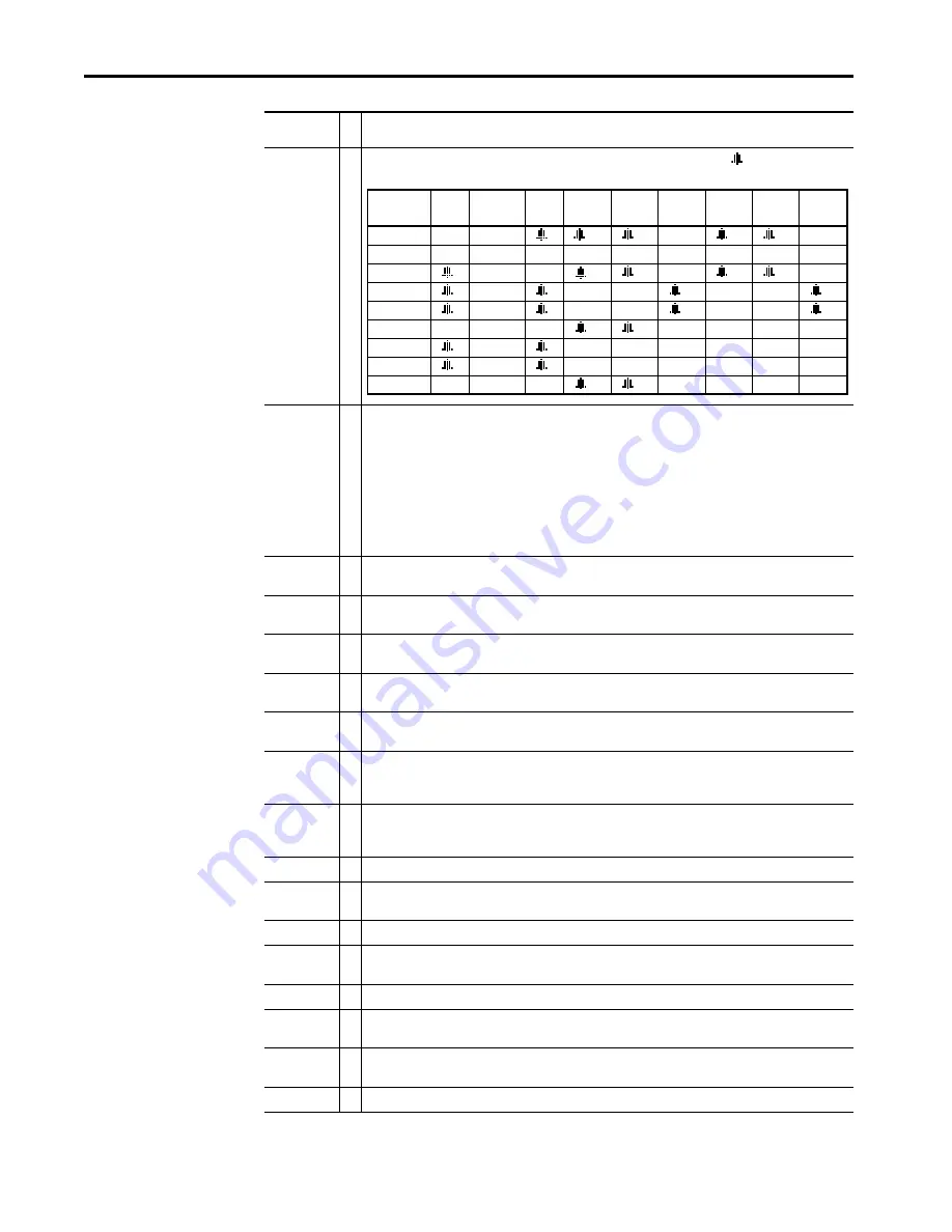
Dig In
ConflictB
User-configurable digital input functions are in conflict. Combinations marked with a
will cause an alarm.
Dig In
ConflictC
More than one physical input has been configured to the same input function. Multiple configurations are not
allowed for the following input functions:
Drive OL
Level 1
The calculated inverter IGBT temperature requires a reduction in PWM carrier frequency. If inverter Drive OL Mode
(150) is disabled and the load is not reduced, an overload fault eventually occurs.
Drive OL
Level 2
The calculated inverter IGBT temperature requires a reduction in Current Limit. If inverter Drive OL Mode (150) is
disabled and the load is not reduced, an overload fault eventually occurs.
Flux Amps Ref
Rang
Result of autotune procedure (inverter 61).
IntDBRes
OvrHeat
The drive has temporarily disabled the dynamic braking regulator because the resistor temperature has exceeded
a predetermined value.
IR Volts Range
The drive autotuning default is Calculate and the value calculated for IR Drop Volts is not in the range of
acceptable values. This alarm should clear when all motor nameplate data is properly entered.
MaxFreq
Conflict
The sum of inverter Maximum Speed (82) and inverter Overspeed Limit (83) exceeds inverter Maximum Freq
(55). Raise inverter Maximum Freq (55) or lower inverter Maximum Speed (82) and/or inverter Overspeed Limit
(83) so that the sum is less than or equal to inverter Maximum Freq (55).
Motor Type
Cflct
Inverter Motor Type (90) has been set to Sync Prm Mag or Sync Reluc, and one or more DC functions (for example,
DC Boost, DC Brake, etc.) have been activated. DC injection functions are incompatible with synchronous motors
and may demagnetize them.
No Line Sync
Rectifier cannot synchronize to the AC line.
NP Hz Conflict
Fan/pump mode is selected in inverter Torq Perf Mode (53), and the ratio of inverter Motor NP Hertz (43) to
inverter Maximum Freq (55) is greater than 26.
Power Loss
Drive has sensed a power line loss.
Power Phased
ACB
Input power phases are connected ACB, two input phases must be switched.
Prechrg Actv
Drive is in the initial DC bus precharge state.
Speed Ref
Cflct
Inverter Speed Ref x Sel or inverter PI Reference Sel is set to
Reserved
.
Under-
Voltage
The bus voltage has dropped below a predetermined value.
VHz Neg Slope
Custom V/Hz mode has been selected in inverter Torq Perf Mode (53) and the V/Hz slope is negative.
Alarm
Ty
pe Description
Start
Stop–CF
Run
Run Fwd Run Rev Jog
Jog Fwd Jog Rev
Fwd/
Rev
Start
Stop–CF
Run
Run Fwd
Run Rev
Jog
Jog Fwd
Jog Rev
Fwd / Rev
Forward/Reverse
Run Reverse
Bus Regulation Mode B
Speed Select 1
Jog Forward
Acc2 / Dec2
Speed Select 2
Jog Reverse
Accel 2
Speed Select 3
Stop Mode B
Decel 2
Run Forward
Run
Summary of Contents for Allen-Bradley LiquiFlo 2.0
Page 1: ...LiquiFlo 2 0 AC Drive User Manual OriginalInstructions ...
Page 6: ...6 Rockwell Automation Publication D2 3518 4 January 2020 Table of Contents Notes ...
Page 8: ...8 Rockwell Automation Publication D2 3518 4 January 2020 Preface Notes ...
Page 12: ...12 Rockwell Automation Publication D2 3518 4 January 2020 Chapter 1 Introduction Notes ...
Page 34: ...34 Rockwell Automation Publication D2 3518 4 January 2020 Chapter 2 About the Drive Notes ...
Page 68: ...68 Rockwell Automation Publication D2 3518 4 January 2020 Chapter 8 Programming Basics Notes ...
Page 267: ......


