Roche OMNI C Instructions For Use Manual Download Page 116

6 Maintenance

6-22

Instructions for Use, Roche OMNI C, Rev. 4.0, December 2002

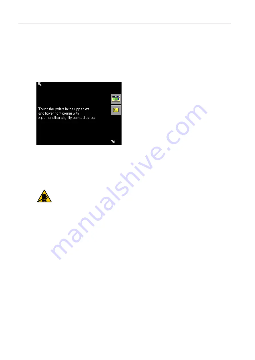
By pressing the "Calibrate" button, you can use a pencil or other pointed object (but which 
is not too hard, to avoid scratching the surface) to touch the white points in the upper left 
and lower right corners. After release, the instrument will accept the exact position. 
From this time on, the instrument will use the touched points to calculate the offset 
between the displayed pixels and the touch screen. After a point has been accepted, the 
arrow disappears. The point itself remains visible and active (pressing the position again 
re-establishes the point) (see Fig. 30).

Fig. 30 

After leaving the window, the new correction values take effect.

6.7

Additional maintenance procedures

The listed maintenance procedures should only be performed by the customer sup-
port or by well-trained personnel. For detailed description, please refer to the Serv-
ice Manual!

Yearly service

Check the baro value

Fill level measurement – waste material: check / correct accuracy

Pump head

Replacement of the entire tubing system

Summary of Contents for OMNI C

Page 1: ...I C Instructions for Use P O I N T O F C A R E T E S T I N G Ident Nr PD0087 Druckvorlage ____ __A M__J_ nderungsstand SP 0132 Bezeichnung Titelblatt OMNIC Instruction for Use Druckvorlagenherstellung...

Page 2: ...duced in any form or communicated to any third party without the prior writ ten consent of Roche Diagnostics While every effort is made to ensure its correctness Roche Diagnostics assumes no respon si...

Page 3: ...rmed only by the manufacturer or qualified service personnel Only accessories and supplies either delivered by or approved by Roche are to be used with the instrument These items are manufactured espe...

Page 4: ...l 2 Do not operate the instrument in an explosive environment or in the vicinity of explosive anesthetic mixtures containing oxygen or nitrous oxide If an object or liquid enters the internal areas of...

Page 5: ...3 Calibration 2 Specifications 1 Introduction 4 Measurement 5 Quality Control 6 Maintenance 7 Trouble shooting 8 Operating Modes 9 Index...

Page 6: ......

Page 7: ...dangers 1 6 1 4 1 Handling samples 1 6 1 4 2 Disposal of waste water bottles electrodes and the instrument 1 6 1 4 3 Decontamination 1 6 1 5 Handling solutions 1 6 1 6 Handling electrodes 1 7 1 7 Sys...

Page 8: ...tube 1 22 13 Insert needle and fill port holder 1 23 14 Insertion of printer paper 1 23 15 Insertion of bottles 1 24 16 Insert electrodes 1 25 17 Insertion of the reference electrode 1 26 18 Begin in...

Page 9: ...suring QC system calibration commonly used functions b Database data about patients measurement calibration QC and the instrument c Setup instrument settings d Info Roche info version number fill leve...

Page 10: ...queous solutions cannot be guaranteed e g due to the possibility of interfering components and or missing or insufficient buffer systems and or differences in ionic strength and diffusion potential wh...

Page 11: ...etely consumed by the indicated date If a day is not indicated apply the last day of the respective month Storage note The conditions necessary to preserve the product s shelf life before opening For...

Page 12: ...or Use All sections passages that are marked with this symbol refer to Instructions for Use describe information to avoid possible potential for personal injury for patients user or third person Risk...

Page 13: ...the other hand the dispersed light is also evaluated Hematocrit Measurement of the sample s conductivity 1 2 2 Calibration procedure tHb and SO2 are calibrated when the instrument is calibrated Ambie...

Page 14: ...ical samples Roche recommends following a decontamination procedure in addition to regulations spe cific to the laboratory These decontamination procedures should be performed periodically to minimize...

Page 15: ...ition the PCO2 electrode during storage is found inside the ALU PE packaging This gas atmosphere ensures immediate potential stability during insertion of the elec trode into the measurement chamber a...

Page 16: ...ady screen Depending on the settings and the status of the instrument the parameter buttons may have the following appearance Pressing the parameter button produces a status report see chapter 7 Troub...

Page 17: ...ration in plasma ctCO2 P Total CO2 concentration in plasma ctCO2 B Total carbon dioxide concentration in blood BE Base deviation of blood BEact Base deviation of blood at current oxygen saturation BEe...

Page 18: ...ent s temperature RIt Respiratory index at patient s temperature AaDO2 t Alveolar arterial oxygen partial pressure at patient s temperature a AO2 t Alveolar arterial oxygen partial pressure ratio at p...

Page 19: ...iagnosis Medication Diet Admission date Admission time Discharge date Discharge time Admission status Location Diagnose code Relig denom Marital status Isolation status Patient language Hospital servi...

Page 20: ...Analyzer operating mode Analyzer operating mode Setup operating mode Database additional functions move one line up down page to the left right additional selection possibilities select the marked ent...

Page 21: ...determining the levels of total hemo globin tHb and oxygen saturation SO2 in whole blood 1 7 5 Pump A peristaltic pump transports the sample and the operating fluids inside the instrument 1 7 6 Flap W...

Page 22: ...adapter when using the serial interface Please order this part from your customer service representative COM 1 This interface can be assigned to a ticket printer and Host FMT For an exact description...

Page 23: ...ch number date of expiry Scanning of patient or user identity Scanning of QC data QC material batch number basis date of expiry target values etc Scanning of desired alphanumeric code IMPORTANT Press...

Page 24: ...C to 31 C 20 to 90 at 31 C to 33 C Allow sufficient free space around the instrument for air circulation and the electrical connections Check for the correct voltage 100 to 240 VAC 10 After setting u...

Page 25: ...into the power supply Fig 9 1 Connect the barcode scanner and if necessary the network cable Fig 9 2 to the respective interface s Fig 9 3 on the reverse side of the Roche OMNI C Fig 9 Open the bottl...

Page 26: ...connect the cord to the power supply Open the AutoQC cover and remove the transport safety band and both safety screws see Fig 12 1 TIP The safety screws are intended to fix the longitudinal and tran...

Page 27: ...e opening on the side wall on the Roche OMNI C and lock into place Fig 13 Connect both tube ends in the bottle compartment to the docking part according to Fig 14 Fig 14 Connect the cable of the AutoQ...

Page 28: ...and confirm your selection with Please see chapter 3 Operating Modes section Setup in the Reference Manual for an exact description 5 Setting the date and time and press Times intervals Date Time Ple...

Page 29: ...en continue by following the instructions on the screen TIP Confirm every step by pressing the button 9 Check tubes at V2 and V9 Check the bottle compartment s back wall to make sure that the air mixt...

Page 30: ...ule Insert the AutoQC ampoule block Close the cover of the AutoQC module Perform the mat assignments and program the AutoQC times Please see chapter 5 Quality Control 12 Attach pump tube Open the inst...

Page 31: ...s into place Fig 20 Rotate the fill port holder so that the underside shows on the top see Fig 21 1 and then push this over the needle see Fig 21 2 CAUTION do not bend the needle when pushing it up Sn...

Page 32: ...r and feed the paper outward through the slit in the printer cover Fig 23 15 Insertion of bottles TIP To avoid splashing the C1 and C2 calibration solutions deaerate the bottles at about 3000 m above...

Page 33: ...ssed the expiration date the screen displays a warning Confirm with the button Remove rubber sealings from C3 Fluid Pack before inserting it Insert the bottle completely into the appropriate position...

Page 34: ...ction Result calibration and measurement errors If necessary remove air bubbles by holding the electrode vertically and by tapping lightly with your fingernail against the electrode body see Fig 27 Fi...

Page 35: ...ion Result calibration and meas urement errors Fig 29 Affix the white plug at the end of the reference electrode tube see Fig 30 IMPORTANT push the plug in completely Fig 30 Close the locking lever In...

Page 36: ...chamber and then the instrument cover 18 Begin installation routines Press All solutions are aspirated and the system is calibrated this may take longer than the respective actions during operation I...

Page 37: ...backup the data to a PCMCIA card or an inter face see chapter 8 Operating modes section Database TIP Roche Diagnostics recommends decontaminating all surfaces and tubing before shutting down the instr...

Page 38: ...ends of the tube onto an absorbent pad such as a paper towel of gauze see Fig 34 Fig 34 3 Insert the shutdown kit and connect it Fill the shutdown kit about halfway with distilled water Insert the shu...

Page 39: ...ure for emptying the tubes by pressing the button 5 Remove the waste water bottle Then remove the waste water bottle W waste container 6 Return the V2 and V9 tube ends to the guides Return the air mix...

Page 40: ...ectrodes Close the locking lever and the measurement chamber cover 9 Remove needle and fill port Open the flap to the labelled capillary position completely open position Rotate the fill port holder i...

Page 41: ...e printer paper Open the printer cover Pull out the printer paper to the rear and remove it Close the printer cover 11 Remove the tube under V1 and V2 Slide the feed tube of the C1 solution under the...

Page 42: ...System stop mode shut down Only a renewed installation procedure can alter this status Switch the instrument OFF Shut down is complete 13 Uninstall the AutoQC module Pull the cable of the AutoQC modul...

Page 43: ...d plastic relief clamp for the AQC valve V17 Fig 43 If you plan to transport the instrument be sure to unplug the power cord the scanner and the network cable Then install the transport safety device...

Page 44: ...1 Introduction 1 36 Instructions for Use Roche OMNI C Rev 4 0 December 2002...

Page 45: ...2 3 2 5 Calibrations 2 3 2 6 Environmental parameters 2 4 2 6 1 Temperature humidity stability 2 4 Instrument 2 4 Electrodes 2 4 Solutions 2 5 Stability during operation 2 5 QC Material 2 6 2 7 Produc...

Page 46: ...2 Specifications 2 II Instructions for Use Roche OMNI C Rev 4 0 December 2002...

Page 47: ...D 1 5 mmHg SD 2 0 mmHg 2 5 mmHg 80 200 mmHg SD 4 5 mmHg SD 6 mmHg 8 mmHg 0 533 2 00 kPa SD 0 267 kPa SD 0 400 kPa 0 533 kPa 2 00 10 664 kPa SD 0 200 kPa SD 0 267 kPa 0 333 kPa 10 664 26 660 kPa SD 0 6...

Page 48: ...dL 7 1 0 78 g dL 30 00 60 00 g L SD 3 0 2 70 g L SD 3 3 3 00 g L 3 3 7 00 g L 60 00 180 00 g L SD 4 50 g L SD 5 00 g L 5 00 g L 180 00 250 00 g L SD 2 1 0 60 g L SD 2 1 1 10 g L 7 1 7 80 g L 1 86 3 72...

Page 49: ...g L 110 0 160 0 g L 10 0 260 0 g L 9 3 mmol L 6 8 9 9 mmol L 6 2 161 3 mmol L P50 26 7 mmHg 15 0 40 0 mmHg 15 0 40 0 mmHg 3 56 kPa 2 00 5 33 kPa 2 00 5 33 kPa FIO2 0 21 0 1 1 0 0 1 1 0 RI 0 84 0 7 2...

Page 50: ...Calibrations Time intervals Length typical min Sys cal every 24 hours alternatively 8 12 or 24 hours 15 1P cal every 30 minutes alternatively 1 hour 2 2P cal every 12 hours alternatively 4 6 8 or 12 h...

Page 51: ...ture 37 C 0 2 C Storage and transportation conditions Temperature 20 C to 50 C Humidity up to 95 not condensed Shock resistance 30 g Operating conditions Operating temperature 37 C Relative humidity 2...

Page 52: ...Temperature 2 to 30 C Humidity 20 to 95 Transportation conditions in original packaging Temperature 2 C to 45 C over a period of 7 days Relative humidity 20 95 Shock resistance 30 g Solutions Descript...

Page 53: ...tation conditions in original packaging Stability during operation Temperature COMBITROL TS AUTO TROL TS 2 bis 8 C 24 months 2 bis 8 C 24 months Temperature COMBITROL TS AUTO TROL TS 28 C max 3 months...

Page 54: ...er 150 W 2 8 2 Classification Protection class I Overvoltage category II Contamination level 2 2 8 3 Dimensions Instrument Width 35 4 cm Height 46 7 cm Depth 41 0 cm AutoQC module Width 19 5 cm Height...

Page 55: ...t 30 m 2 10 Screen Type integrated flat LCD screen Format 5 7 inch Resolution 320 x 240 pixel 2 11 Barcode scanner Type MT 9060 4 Wedge PS2 hand held scanner with integrat ed decoder Manufacturer Mars...

Page 56: ...2 Specifications 2 10 Instructions for Use Roche OMNI C Rev 4 0 December 2002...

Page 57: ...1 3 1 2 2P calibration 2P cal 3 1 3 1 3 1P calibration 1P cal 3 1 3 1 4 Recalibration 3 1 3 2 User activated calibrations 3 2 3 2 1 Calibration for Ready 3 2 3 2 2 System calibration 3 2 3 2 3 Conduc...

Page 58: ...3 Calibration 3 II Instructions for Use Roche OMNI C Rev 4 0 December 2002...

Page 59: ...includes the following Cleaning with internal cleaning solution Automatic conditioning of the Na electrode every 24 hours Calibration of the mixing system 2 point calibration of all parameters TIP Th...

Page 60: ...calibration incl O2 2P O2 calibration 2P calibration without O2 Press System Fig 1 Using the up down buttons you may now select the desired calibration Start the selected calibration by pressing the b...

Page 61: ...ing ratio in combination with the mixing system 3 2 4 1P calibration This calibration is a 1 point calibration incl O2 of all parameters 3 2 5 2P calibration incl O2 This calibration is a 2 point cali...

Page 62: ...3 Calibration 3 4 Instructions for Use Roche OMNI C Rev 4 0 December 2002...

Page 63: ...ts 4 1 Sample collection especially for tHb SO2 and Hct measurement 4 1 4 1 2 Sample collection containers 4 2 Syringes 4 2 Capillary tubes 4 2 Microsampler 4 2 Clot catcher 4 3 4 1 3 Sample handling...

Page 64: ...4 Measurement 4 II Instructions for Use Roche OMNI C Rev 4 0 December 2002...

Page 65: ...ies in the mea surement values See for example NCCLS document H11 A2 Percutaneous Collection of Arterial Blood for Laboratory Analysis Second Edition Approved Standard May 1992 for detailed informatio...

Page 66: ...he capillary tubes must have a minimum volume of 100 l Capillary tubes with ceramic sealing caps should not be used because the fracture that forms when opening the capillary can damage the fill port...

Page 67: ...ood for example when sampling blood of newborns blood from ear lobes and blood from heels The clot catcher prevents blood clots and tissue particles from entering the Roche OMNI C The clot catcher can...

Page 68: ...y after sampling to ensure correct and accurate measurement results Despite proper sampling procedures errors can arise in the blood gas analysis due to insufficient mixing of the sample following rem...

Page 69: ...rt a measurement the Roche OMNI C must be Ready and in the Analyzer 1 operating mode Depending on the settings the entry of a password or a mandatory input input value may be required see Reference Ma...

Page 70: ...tes the interior of the syringe or ampoule in order to remove the sample without air bubbles Be sure that the needle does not make contact with the fill port while inserting the nee dle into the inter...

Page 71: ...he OMNI C Rev 4 0 December 2002 4 7 Fig 4 Upon display of the instruction Close flap remove the syringe and close the flap The measurement starts TIP Never open the flap during measurement Doing this...

Page 72: ...liquid that are on the needle tip Fig 5 Insert the capillaries or the microsampler into the fill port The end of the capillary must be open otherwise the aspiration process is blocked and the sample...

Page 73: ...rious patient operator and sample specific data may be entered You may use a standardized or a user specific form when entering data TIP Scanning of patient and operator data is possible You can creat...

Page 74: ...the screen before printing the results Use the menu selection Setup Displays reports Measuring data Result screen to create a user specific results display see Reference Manual chapter Operating mode...

Page 75: ...u can complete or edit additional entries in the database For more information refer to chapter 8 Operating modes section Database in these Instructions for Use and to the respectively titled chapters...

Page 76: ...4 Measurement 4 12 Instructions for Use Roche OMNI C Rev 4 0 December 2002...

Page 77: ...ner to enter data 5 3 Manual entry 5 3 5 4 Inserting AutoQC mats 5 4 5 4 1 Material assignment AutoQC materials 5 4 5 4 2 Setting QC times 5 6 5 5 QC measurement 5 9 5 5 1 Manual QC measurement 5 9 5...

Page 78: ...5 Quality control 5 II Instructions for Use Roche OMNI C Rev 4 0 December 2002...

Page 79: ...patients In order to ensure the quality of the measurement results complete a quality control test on 3 levels low normal high after each electrode exchange and after startup of the instru ment at lea...

Page 80: ...outside the target value range 3 Consequence The parameter receives the QC consequence QC error The QC measurement result is not acceptable The parameter is locked for additional mea surements and may...

Page 81: ...QC materials with 4 levels each can be entered Fig 1 Use the line down button to select the material to be changed or to select a new QC mate rial Using the barcode scanner to enter data Use the barc...

Page 82: ...xt insert the mats in the ampoule block with the ampoule necks pointing down see Fig 2 1 Fig 2 Place the mat in the defined position A F of the ampoule block the ampoules must no longer be visible see...

Page 83: ...of insufficient or empty ampoules The number of ampoules is reset to 20 The selected material can be deleted from the mat position TIP The preprogrammed times see the section Setting QC times must be...

Page 84: ...ct the start time s for the AutoQC measurement s and or the time for performing a manual QC measurement After reaching the set time a note appears in the message window Fig 6 Up to 16 time entries per...

Page 85: ...l or Settings QC Material Set ranges Confirm the selection with Enter the start time Any number of materials and times can be selected Press the attributes of the time entries can be edited Copying a...

Page 86: ...Instructions for Use Roche OMNI C Rev 4 0 December 2002 More functions Measurement retries The number of repeated measurements none 0 1 2 that are allowed in the case of an incorrect measurement can b...

Page 87: ...level 1 Remove the ampoule of the corresponding level of the desired QC material from the packaging or of the AutoQC material from the mat Gently tap the head of the ampoule with your fingernail to r...

Page 88: ...the ampoule and close the flap The measurement starts automatically If the user does not reject the results they are printed and automatically saved in the QC database Details about the operating mode...

Page 89: ...rations A mini mum of 2 QC measurements series or 6 QC measurements 3 series is required The QC concept expects Multirules rule 1 and 2 to be activated Press the following buttons to check the setting...

Page 90: ...rule process is applied after each individual measurement Multirules are only applied to the corresponding control material e g COMBITROL TS Rule Description 1 12 QC measurement value m is outside 2 2...

Page 91: ...nsequences Parameter Miscellaneous settings QC Consequences Fig 13 Description of the QC consequences Ignore if one of the set rules is broken no consequences will be set QC warning through a warning...

Page 92: ...the same material level combination is no longer available In this case repeat the QC measurement with a new material level combination of a different batch and analyze it as described under 5 2 Impo...

Page 93: ...bration solution 1 C2 calibration solution 2 and C3 fluid packs 6 7 C1 calibration solution 1 and C2 calibration solution 2 6 7 C3 fluid pack 6 7 6 5 2 Waste material 6 9 Remove the waste container W...

Page 94: ...II Instructions for Use Roche OMNI C Rev 4 0 December 2002 6 6 8 Surfaces 6 20 6 6 9 Adjusting the screen 6 21 6 7 Additional maintenance procedures 6 22 6 8 Maintenenance overview 6 23 6 9 Maintenanc...

Page 95: ...Use only liquid disinfectant such as protein remover Roche deproteinizer or an alcohol based about 70 surface disinfectant Do not spray disinfectant directly onto the instrument because this could cau...

Page 96: ...d from the tubes by briefly holding the tubes vertically allowing the fluid to run back into the container Empty the container according to local regulations and fill the shutdown kit halfway with dis...

Page 97: ...xidizing character of this preparation we cannot rule out local irritation to the skin eyes and mucous membranes First Aid measures After inhalation breath fresh air drink large amounts of water After...

Page 98: ...tles bottles whose usage date has expired and full waste water bottles see section Using the empty C1 calibration solution 1 bottle as W waste container page 6 11 6 2 2 Check printer paper Check daily...

Page 99: ...nalyzer operating mode press System Wash and clean Clean sample port module Fig 3 Open the flap to the labelled capillary position completely open position Use a moist deproteinizer for example paper...

Page 100: ...cover tension lever Push the linear clamp white plastic part upwards see Fig 5 1 Remove the complete tubing set tubing holder and tubing see Fig 5 2 Fig 5 Check if the five rollers on the peristaltic...

Page 101: ...he bottles may never be mixed together because this may result in calibration errors Reuse of this bottle can lead to errors during calibration Insert another bottle that has not yet expired C3 fluid...

Page 102: ...tion date the screen displays a warning Reuse of this bottle can lead to errors during calibration Insert another bottle that has not yet expired Remove rubber sealings from C3 Fluid Pack before inser...

Page 103: ...nt cover The bottle exchange image appears on the display see Fig 8 Fig 8 Always wear gloves Danger of infection Open the docking mechanism and remove the waste container Dispose of the waste containe...

Page 104: ...nter clockwise Fig 10 Fig 10 When removing the screw cap make sure that the green element inside the bottle is not moved or removed Fig 11 Fig 11 Empty the waste material and decontaminate the contain...

Page 105: ...eature recognizes the waste container as empty When inserting a bottle that is not completely empty press the button A numerical keyboard appears on the display Enter the approximate fill level in and...

Page 106: ...s System Wash and clean Clean sample port module Open the flap to the labelled capillary position completely open position Rotate the fill port holder in the direction of the arrow see the marking on...

Page 107: ...or Use Roche OMNI C Rev 4 0 December 2002 6 13 Snap the fill port holder evenly onto the axis do not bend the needle Fig 15 Close the flap Dispose of the used fill port holder in accordance with local...

Page 108: ...W waste container page 6 11 and Installing the waste water container page 6 11 TIP Do not scan a barcode While in the Analyzer operating mode press System Tools Fluid actions Auto preparation routine...

Page 109: ...clean the wash plate under running water Then dry well Then push the wash plate back in completely and attach the tube plug Push the sample drip tray in Close the flap Close the bottle compartment cov...

Page 110: ...nto the printer Fig 19 Close the printer cover and feed the paper outward through the slit in the printer cover 6 6 4 Replacement of the electrodes and the MCon Open the top cover and measurement cham...

Page 111: ...e replaced with a dummy electrode Prevent the formation of gas bubbles in the inner electrolyte of the electrodes see Fig 22 1 If necessary remove air bubbles by holding the electrode vertically and b...

Page 112: ...tically starts After completing the calibration perform a quality control measurement on all three levels While doing so note the conformance of the results with the target values see chapter 5 Qualit...

Page 113: ...reference solution resulting in calibration and measurement errors Affix the white plug at the end of the reference electrode tube see Fig 26 IMPORTANT push the plug in completely Close the locking l...

Page 114: ...ntaminate any part of the instrument before shutting it down and unplugging it from the power source Before plugging the instrument back in and turning it on always wait 15 minutes to allow the disinf...

Page 115: ...While in the Analyzer operating mode press Test PC components Touch screen Use this test function to test the functionality of the touch screen and to adjust the screen Fig 28 By pressing the Test bu...

Page 116: ...the displayed pixels and the touch screen After a point has been accepted the arrow disappears The point itself remains visible and active pressing the position again re establishes the point see Fig...

Page 117: ...te sample port module Decontaminate screen Replace fill port holder Upcoming services are displayed in red in the list marks the service as performed The next cycle period is calculated marks the serv...

Page 118: ...6 Maintenance 6 24 Instructions for Use Roche OMNI C Rev 4 0 December 2002...

Page 119: ...nductivity cal error 7 5 7 2 8 3010 AQC cover open 7 5 7 2 9 3012 User system stop 7 6 7 2 10 3013 Fluid pack switch 7 6 7 2 11 3014 Fill level alarm 7 6 7 2 12 3015 Waste container full 7 7 7 2 13 30...

Page 120: ...7 Trouble shooting 7 II Instructions for Use Roche OMNI C Rev 4 0 December 2002...

Page 121: ...he system stops and to bring the analyzer back to Ready A stop of all running actions will occur if danger for the user e g by an overflow of the waste while opening the docking mechanism of the waste...

Page 122: ...e a system calibration has been started in the menu System it can not be conducted immediately because the system stop has to be removed first After all system stops have been removed system stop cons...

Page 123: ...an electrode s system calibration 7 2 2 3002 Bottle compartment cover open Cause The bottle compartment is open The bottle compartment cover micro switch is defective Remedy Close bottle compartment...

Page 124: ...recurrence call customer service Consequence actions Wash 7 2 4 3004 Analyzer error Cause The measurement progress was incorrect Remedy Press OK button Switch the analyzer off on In case of recurrence...

Page 125: ...dy Reduce raise the room temperature In case of recurrence call customer service 7 2 7 3009 Conductivity cal error Cause The conductivity calibration has failed Remedy Press the OK button start a syst...

Page 126: ...sors Monitoring sensors In case of recurrence call customer service change if necessary Consequence actions Auto preparing of Fluid Pack C3 solutions 7 2 11 3014 Fill level alarm Cause The solutions C...

Page 127: ...functions System Test Control sen sors Monitoring sensors In case of recurrence call customer service change if necessary Consequence actions Waste container fill level measurement 7 2 14 3017 Pump ca...

Page 128: ...ion Remedy Perform the installation procedure see chapter 1 Introduction section Installation 7 2 17 3020 Economy mode Cause The economy mode has been started manually or automatically Remedy Manual t...

Page 129: ...has less than 8 KB space left for saving additional data Remedy Delete data records from the PCMCIA card in order to free up additional memory capacity insert the card into a PC that has a suitable po...

Page 130: ...you press the parameter button a status report will give you information about why the parameter could not be calibrated see Abb 3 Abb 3 Remedy for the example in Fig 3 Start Calibration for Ready see...

Page 131: ...1 Sensor status For additional information about the sensor status press and Sensor status Press line up line down and select a sensor from the list on the left You receive the following information a...

Page 132: ...7 Trouble shooting 7 12 Instructions for Use Roche OMNI C Rev 4 0 December 2002...

Page 133: ...8 1 4 Quick Access 8 4 8 1 5 QC measurement 8 4 8 2 Setup 8 4 8 3 Database 8 5 Data export PCMCIA card for example 8 7 8 3 1 Patient data 8 9 8 3 2 Measuring data 8 9 8 3 3 Calibration data 8 10 8 3 4...

Page 134: ...8 Operating modes 8 II Instructions for Use Roche OMNI C Rev 4 0 December 2002...

Page 135: ...info version numbers fill levels help sensor status 8 1 Analyzer The Analyzer operating mode contains parameter information for example Ready system settings and the QC measurement The highest level o...

Page 136: ...covered by the password window but the parameter section remains visible parameter information Fig 3 Press the button and enter the required password The measurement can then be started TIP When a ma...

Page 137: ...e following functions may be activated Fig 4 8 1 3 System The following main menus are available Fig 5 Select the appropriate function Activate the marked entry Back to the top level of the analyzer m...

Page 138: ...tart the following actions or change the following settings Fig 6 8 1 5 QC measurement This function helps start a quality control measurement For more detailed information see chapter 5 Quality contr...

Page 139: ...operating mode 8 3 Database Use this function to retrieve the following data Fig 8 TIP You can activate the desired database directly by pressing the respective line on the screen The following query...

Page 140: ...te is at the top Sort criteria OpID Only for measurement data Up arrow the records are arranged in ascending order Down arrow the records are arranged in descending order Sort criteria patient ID Only...

Page 141: ...d data range see the Reference Manual chapter Operating Modes section Data base Delete data Screen shot of the database overview A list of all available forms is displayed user speci fic and standard...

Page 142: ...se be sure that the card is inserted correctly see Fig 11 Fig 11 Press and then The following screen appears Fig 12 After completing all entries press The data is exported Please see the Reference Man...

Page 143: ...data Fig 13 Press these buttons to scroll through all parameters Select the marked entry the patient s data is shown 8 3 2 Measuring data Fig 14 Press these buttons to scroll through all parameters Se...

Page 144: ...rs Select the marked entry the results screen of this calibration is then displayed 8 3 4 QC data Fig 16 When you start this function the Roche OMNI C displays an overview of the saved QC data This sc...

Page 145: ...the results display of the selected QC data are displayed 8 3 5 Instrument data Fig 17 When you start this function an overview of the saved instrument data is displayed Press these buttons to scroll...

Page 146: ...Setup Instrument Roche info see Reference Manual chapter 3 Operating modes section Setup 8 4 2 Version numbers This lists the software version 8 4 3 Fill levels Use this function to check the fill le...

Page 147: ...ev 4 0 December 2002 8 13 8 4 6 Counter overview Fig 20 Lifetime sample counter Number of all measured samples since initial startup Sample counter Number of measurements QC counter Number of QC measu...

Page 148: ...8 Operating modes 8 14 Instructions for Use Roche OMNI C Rev 4 0 December 2002...

Page 149: ...en 6 20 Surfaces 6 20 Wash plate 6 14 Cleaning decontamination 6 1 Cleaning of the needle and fill port 6 5 Cleaning the measurement chamber 6 20 Cleaning the screen 6 20 Clot catcher 4 3 COM 1 1 14 C...

Page 150: ...verview 5 12 O Operating Instructions 1 2 Operating modes 8 1 Overview of the Multirules 5 12 P Parameter Display on the Ready screen 1 8 Method of notation Calculation values 1 9 Calculation values a...

Page 151: ...t 1 13 printer 1 13 Pump 1 13 reverse side 1 14 Sample insertion module 1 13 Screen 1 8 System stop 3001 Measuring chamber cover open 7 3 3002 Bottle compartment cover open 7 3 3003 Flap open 7 4 3004...

Page 152: ...Index 4 Instructions for Use Roche OMNI C Rev 4 0 December 2002...

Reviews: