GENERAL
14
L1
PE
N
T1
T2
S3
B4
BR
RE
DAI
CC
NC
S3
T2
N
NC
LV
FU
LR
2
1
C
TR
CO1
CO1A
A
4
D
1
C
3
B
2
COMG
MO1
2
1
C
TM
Brown
Yellow-green
Blue
Black
White
Red
2 3
1
4 5 6 7 8 9 10 11 12
5
1
3
8
7
6
2
4
K1
L1
NP
ET
A
TA
NP
I
LP
IP
E
2
1
C
TS
TA
2
1
C
TF
L
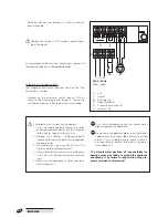
Electrical connections to be made
by the heating engineer
NP
E
230 V~50 Hz
Power supply
PI
FuNCTIONAl WIRING DIAGRAMS
INSIEME CONDENS 26 B - 35 B
COMG
-
4 position function selector
TF
-
Flue gas ther
mostat (90°C)
TS
-
Safety ther
mostat (110°C)
TM
-
Minimum temperatur
e ther
mostat
(40°C)
TR
-
Boiler contr
ol ther
mostat (33 - 82°C)
K1
-
Bur
ner contr
ol r
elay
LV
-
Mains power indicator
LR
-
Bur
ner lockout indicator
FU
-
Mains power fuse 6.3 A-T
CO1
-
12 pin connector
BR
-
Bur
ner connector
MO1
-
T
er
minal strip
Connections to be made by the heating engineer PI
-
CH pump
TA
-
Room ther
mostat
D
A
I
-
Automatic
shut-of
f
device
(not
supplied;
only
wher
e
requir
ed;
see
also
the
"Fuel
connections"
section).
The
automatic
shut-of
f device
(DAI)
and
the
relay
(RE)
must
be
suitable
for
a
230
VAC
power supply
.
RE
-
Relay (not supplied)


