TECHNICAL ASSISTANCE SERVICE
44
1
2
3
4
5
6
7
8
ACCESSING THE NOZZLE, FLAME GUIDE
AND ELECTRODES
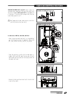
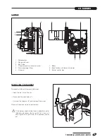
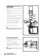
Proceed as follows to access the nozzle, flame guide and
electrodes:
- Unscrew and remove the fixing nut from the flange and
remove the burner.
- Loosen the screws (1) and pull out the blast tube as-
sembly (2)
- Loosen the screw (4) and remove the flame guide hold-
er (6) from the nozzle holder (7).
- Completely unscrew the fixing screw and pull out the
fibre optic cable (4) from the flame guide holder (6).
- Disconnect the cables (5) from the electrodes.
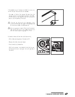
- Replace the nozzle (8), taking care to screw it in and
tighten it correctly as shown in the figure.
Reverse the above steps to reassemble.
a
It is strictly forbidden to use nozzles of different
make, type and specifications to the original.
4,5 - 0,5 mm
3
±
0,3 mm
1
2
4 5
3
5,5
±
0,3 mm
POSITIONING THE ELECTRODES
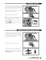
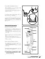
Correct electrode positioning is essential for efficient igni-
tion and combustion.
Proceed as follows to set electrode position.
- Engage the flame guide holder (1) with the nozzle
holder (2) and secure it with the screw (3).
- Loosen the screw (5) to set the electrodes (4) in the
right position.
a
It is forbidden to change the positions and dimen-
sions given.


