INSTALLER
28
6
7
8
9
10
11
L1
PE TA TA
1
2
3
4
5
N
L1
PE TA TA
1
2
3
4
5
N
L1
PE
N
L1
PE
1
2
3
N
230 V~50 Hz
Alimentazione elettrica
PI
G
TA
b
The following instructions are mandatory:
1 - Use a multi-pole magnetic thermal trip switch
and disconnector conforming to EN standards
(with a contact gap of at least 3 mm).
2 - Respect the L (Phase) - N (Neutral) polarity.
Keep the ground wire about 2 cm longer than
the power wires.
3 - Use cables with a cross section of 1.5 mm2 or
more, complete with end terminals.
4 - Always refer to the electrical wiring diagrams
in this manual when performing any electrical
work.
5 - Make sure the appliance is connected to an
efficient ground.
a
It is strictly forbidden to use fuel and/or water
pipes to ground the appliance.
a
Do not route the power cable or room thermostat
cables near hot surfaces (like heating circuit flow
pipes). Use a suitable class of cable if there is
any possibility of contact with parts at tempera-
tures above 50°C.
The manufacturer declines all responsibility for
damage caused by failing to ground the appliance
adequately or by failure to respect the wiring dia-
grams provided in this manual.
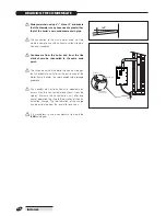
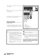
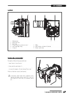
- Make the electrical connections as shown in the dia-
gram alongside.
b
Remove the jumper (TA-TA) before connecting a
room thermostat.
On completion of the electrical connections, replace all
removed components in the opposite order.
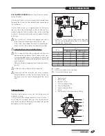
Automatic shut-off device (DAI)
(not supplied; only where required; see also the "Fuel
connections" section).
- Connect up the automatic shut-off device (DAI) as
shown in the wiring diagram on page 14. This ensure
that fuel only passes when the burner is functioning.
Power supply
L1 Live
N Neutral
PE Earth/ground
TA Room thermostat
PI CH pump (accessory kit)
G Terminal strip


