background image

TECHNICAL ASSISTANCE SERVICE 

48

Clean  the  boiler  and  remove  any  carbon  deposits  from 
the surfaces of the heat exchanger 

at least once a year

This  not  only  extends  the  boiler’s  working  life,  but  also 
keeps  it  efficient  in  terms  of  heat  output  and  consump-
tion.

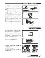
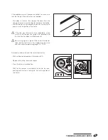
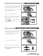
Before performing any cleaning operation: 

- Switch the electricity supply OFF at the system’s main 

switch  and  turn  the  control  panel  function  selector  to 
OFF (

I

- Close the fuel shut-off cocks.

EXTERNAL CLEANING

Clean the boiler’s casing panels and control panel with a 
soft cloth damped in soapy water.
To remove stubborn marks, use a cloth damped in a 50% 
mix of water and denatured alcohol or a suitable cleaning 
product.
Wipe the boiler dry after cleaning it.

Do not use abrasive products, petrol or triethylene.

INTERNAL CLEANING

To ensure that the boiler remains efficient, 

change the burner nozzle and check the smoke 

scale reading at every annual maintenance.


Also check combustion conditions at regular 

intervals during normal functioning.

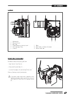
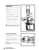
Proceed  as  follows  to  access  the  internal  parts  of  the 

boiler:

-  Remove the front and top panels (1) and (2)
-  Remove the burner (see page .43)

Cleaning the boiler body

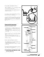
-  Release the clips (3) and remove the cover (4) from the 

flue gas box

-  Remove  the  turbulators  (5)  and  check  them  for  wear. 

Replace as necessary.

-  Clean  the  flue  gas  path  with  a  flue  brush  or  other 

suitable tool and remove any soot through the hole in 
the combustion chamber. Take care not to damage the 
flame guard (6).

b


Do not use chemical solvents or detergents to clean 
the heat exchanger.

DISASSEMBlING AND ClEANING THE BOIlER

1

2

20

40

60

80
100

0

120

3

5

7

4

9

8

Summary of Contents for 20039590

Page 1: ...1 INSTALLATION AND MAINTENANCE MANUAL CONDENSING BOILERS 26 B 26 BK 35 B 35 BK 26 BK 35 BK 26 B 35 B ...

Page 2: ...NSIEME CONDENS 26 BK 20040647 INSIEME CONDENS 35 BK 20040447 INSIEME CONDENS r condensing boilers conform to the following directives Efficiency Directive 92 42 EEC HHHH Electromagnetic Compatibility Directive 2004 108EEC Low Voltage Directive 2006 95EEC 0694 CONFORMITY RANGE ...

Page 3: ... service and to provide comfort in the home for many years to come This manual provides information that is essential to the installation of the appliance Used in conjunction with your own knowledge and expertise it will enable you to install the appliance quickly easily and correctly Once again please accept our thanks and our congratulations on your choice of product Riello S p A ...

Page 4: ... Installation in older systems and systems requiring modernisation 20 Water in heating circuits 20 Water connections 23 Draining the condensate 26 Electrical connections 27 Fuel connections 29 Flue gas vent and comburent air intake 30 Filling and emptying the system 33 TECHNICAL ASSISTANCE SERVICE Page Preparing for initial start up 37 Initial start up 37 Checks during and after initial start up 4...

Page 5: ... freezing bLow temperature under floor heating systems must be fed through a circuit fitted with a mixer valve bThe boiler must be serviced at least once a year bThis instruction manual is an integral part of the boil er It must be kept safe and must ALWAYS accom pany the boiler even if it is sold to another owner or transferred to another user or to another installation If you damage or lose this...

Page 6: ...he electromechanical control panel conform to all applicable technical and safety standards A specific accessory kit is available to control a high tem perature central heating circuit Additional controllers can also be added to manage additional direct mixed circuits or to integrate the boiler with r solar water heating systems PRODUCT DESCRIPTION SAFETY DEVICES INSIEME CONDENS boilers are equipp...

Page 7: ...TIPO TYP TYP TYPE TIPO TIPO COMBUSTIBILE COMBUSTIBLE BRENNSTOFF BRANDSTOF FUEL COMBUSTIBLE COMBUSTÍVEL PAESE DI DESTINAZIONE PAYS DE DESTINATION BESTIMMUNGSLAND LAND VON BESTEMMING COUNTRY OF DESTINATION PAÍS DE DESTINO PAÍS DE DESTINO European Directive 92 42 EEC Pms bar T C Qn min Pn min T067676G1 Qn max Pn max Mod Cod N kW kW kW kW kW D l min kW kW kW Pmw bar T C IP W V Hz RIELLO S p A Via Ing ...

Page 8: ...t valve 4 Automatic vent valve collector 5 Boiler sensor sockets 6 Fitting for CH circuit safety valve 7 Fitting for CH circuit expansion vessel 8 Flame inspection window 9 Burner 10 Condensate drain siphon 11 Socket for flue gas thermostat 12 Insulated boiler body 13 Insulated secondary heat exchanger 14 Flue gas vent pipe 15 Cover panel 16 Front panel 17 Boiler drain cock 18 Lifting points 19 Fl...

Page 9: ...Fitting for CH circuit expansion vessel 8 Flame inspection window 9 Burner 10 120 litre insulated storage cylinder 11 Storage cylinder drain cock 12 Condensate drain siphon 13 Socket for flue gas thermostat 14 Insulated boiler body 15 Insulated secondary heat exchanger 16 Flue gas vent pipe 17 Cover panel 18 Front panel 19 Boiler drain cock 20 Lifting points 21 Storage cylinder temperature sensor ...

Page 10: ...ted 25 33 3 kW Useful efficiency at max Pn 80 60 C 96 1 96 5 Useful efficiency at 30 Pn return temp 47 C 96 3 96 5 Useful efficiency at max Pn 50 30 C 101 2 101 4 Useful efficiency at 30 Pn return temp 30 C 101 5 100 8 Combustion efficiency 97 8 97 7 Losses on shutdown 370 370 W Boiler side pressure drop at rated heat input 20 31 mbar Maximum residual pressure in flue gas vent 15 40 Pa Flue gas te...

Page 11: ...ssel accessory model 26 B 35 B only 20041976 3 bar safety valve accessory model 26 B 35 B only 20042167 Remote storage cylinder connection accessory models 26 B 35 B only 20012799 120 ATRB storage cylinder connection accessory models 26 B 35 B only 4047692 Storage cylinder interface kit only for models 26 B 35 B with remote storage cylin der connection buffer tank code 20012799 4047490 Total shutd...

Page 12: ...sensor 3 Boiler temperature gauge sensor 4 Safety thermostat sensor 5 Maximum temperature thermostat sensor 6 Storage cylinder thermostat sensor 7 Storage cylinder temperature gauge sensor 8 Flue gas thermostat sensor INSIEME CONDENS 26 B 35 B 1 Boiler thermostat sensor 2 Minimum temperature thermostat sensor 3 Boiler temperature gauge sensor 4 Safety thermostat sensor 8 Flue gas thermostat sensor...

Page 13: ...00 450 500 600 550 26 B BK 35 B BK PUMPS aNever run the pump dry r INSIEME CONDENS boilers come without a pump A pump must therefore be provided as part of the installation In order to choose a pump of the right size bear in mind the boiler s water side pressure drop as shown in the figure below FLOW RATE l h PRESSURE DROP mbar ...

Page 14: ...ion function selector TF Flue gas thermostat 90 C TS Safety thermostat 110 C TM Minimum temperature thermostat 40 C TR Boiler control thermostat 33 82 C K1 Burner control relay LV Mains power indicator LR Burner lockout indicator FU Mains power fuse 6 3 A T CO1 12 pin connector BR Burner connector MO1 Terminal strip Connections to be made by the heating engineer PI CH pump TA Room thermostat DAI A...

Page 15: ...nter selector TF Flue gas thermostat 90 C TS Safety thermostat 110 C TM Minimum temperature thermostat 40 C TR Boiler control thermostat 33 82 C INSIEME CONDENS 26 BK 35 BK TL Maximum temperature thermostat 82 90 C TB Storage cylinder thermostat 0 70 C K1 Burner control relay LV Mains power indicator LR Burner lockout indicator FU Mains power fuse 6 3 A T CO1 12 pin connector CO2 9 pin connector B...

Page 16: ...ctrical power indicator Lights to show that the system is receiving electrical power 5 Burner lockout indicator Lights to show that a burner lockout has occurred 6 Manual reset for safety thermostat Allows you to reset the boiler if the safety thermostat trips Unscrew the protective cover to access the reset button 7 Function indicators 8 Manual reset for flue gas thermostat Allows you to reset th...

Page 17: ...ut indicator Lights to show that a burner lockout has occurred 6 Summer I Winter II selector 7 Storage cylinder temperature gauge Displays the temperature of the domestic hot water 8 Manual reset for safety thermostat Allows you to reset the boiler if the safety thermostat trips Unscrew the protective cover to access the reset button 9 Storage cylinder thermostat Allows you to set the temperature ...

Page 18: ...ulic test certificate Non return valve bThe instruction manual is an integral part of the boiler Once located read it thoroughly and keep it safe P H L P H L DIMENSIONS AND WEIGHT UNPACKING THE PRODUCT Description INSIEME CONDENS 26 B 35 B 26 BK 35 BK L 600 600 600 600 mm P 865 865 1015 1015 mm H 1025 1025 1650 1650 mm Net weight 120 120 200 200 kg INSIEME CONDENS 26 BK 35 BK INSIEME CONDENS 26 B ...

Page 19: ... pallet Make sure that the equipment used to move the boiler is adequate for the weight involved Insert two 3 4 pipes 3 through the lifting points 4 inside the boiler and lift the boiler carefully off the pallet bWear suitable personal protective equipment and use suitable safety devices aDo not leave packaging material within the reach of children since it can become a potential hazard Dispose of...

Page 20: ...me generated by thermal ex pansion Make sure that the central heating circuit has been flushed out to remove all sludge and lime scale and that it has been bled and seal tested Make sure that a suitable water treatment system is in stalled See the Water in central heating systems sec tion Refer to the r catalogue for details of specific products bThe manufacturer declines all responsibility for da...

Page 21: ...phides mg l 10 Nitrides mg l 10 Iron mg l 0 5 2 Central heating systems b Do not use automatic filling devices to add water to central heating systems Use a manual device instead and record top ups in the system service book b If a system comprises a number of boilers when that system is first put into service make sure that all the boilers function simultaneously or on a short interval rotation b...

Page 22: ...central heating systems If oxygen enters a circuit continuously or even intermittently e g in under floor heating systems whose pipes are not protected by impermeable synthetic sheaths in circuits with open expansion vessels or in circuits that require frequent top ups always separate the boiler s water circuit from the central heating circuit Mistakes to avoid and precautions From what has been s...

Page 23: ...he safety valve bCircuits filled with anti freeze must be fitted with water disconnectors bLow temperature under floor heating systems must be fed through a circuit fitted with a mixer valve bThe choice of system components and the method of their installation are left up to the heating engi neer installing the system Installers must use their expertise to ensure proper installation and function i...

Page 24: ...r filter 8 Pressure reducer MI CH flow RI CH return INSIEME CONDENS 26 B 35 B INSIEME CONDENS 26 BK 35 BK 1 Isolating valve 2 Non return valve 3 CH circuit pump 4 CH circuit expansion vessel also available as accessory 5 CH circuit safety valve also available as accessory 6 Drain 7 Softener filter 8 Pressure reducer 9 DHW safety valve also available as accessory 10 CH circuit expansion vessel also...

Page 25: ...w RI CH return MC To SC from boiler RC Return from SC to boiler M To SC from collector R Return from SC to collector PB Solar storage cylinder heating pump PI Central heating pump PR DHW recirculation pump PS Solar circuit pump SE Outdoor temperature sensor SC Boiler temperature sensor SZ Zone temperature sensor SB1 Storage cylinder top temperature sensor SB2 Storage cylinder bottom temperature se...

Page 26: ...e boiler stands must be per fectly horizontal and flat over the entire area of the boiler frame in order to avoid condensate drainage problems b Any condensate neutralisation units deemed nec essary may be connected downstream from the siphon Evaluate the neutralisation unit after one year of operation to estimate the duration of the neu tralisation charge The total duration of the charge can be e...

Page 27: ...d for installation are those to the control panel terminal strip Proceed as follows to access the control panel terminal strip Remove the front and top panels A and B Unscrew the screws C and remove the cover D Route the power cable E through the cable clamp F and fix it in place Access the terminal strip G A B C D G F E G ...

Page 28: ...wer cable or room thermostat cables near hot surfaces like heating circuit flow pipes Use a suitable class of cable if there is any possibility of contact with parts at tempera tures above 50 C The manufacturer declines all responsibility for damage caused by failing to ground the appliance adequately or by failure to respect the wiring dia grams provided in this manual Make the electrical connect...

Page 29: ...n out the oil tank at suitable intervals bThe oil feed line must be suitable for the flow rate demanded by the burner The oil feed system must also be equipped with all the necessary safety and control devices required by applicable legislation and standards Refer to the table alongside for oil feed line charac teristics bA filter must be installed in the oil feed line bMake sure that the oil retu...

Page 30: ...stream fan Comburent air intake directly from the room where the boiler is installed Flue gas vent via horizontal or vertical flues with air ventilation to room B23P As B23 but with flue gas vent designed to operate at positive pressure C13 Concentric wall vent Twin flue pipes can also be used but the wall through pipes must be concentric or located close enough to be subjected to similar wind con...

Page 31: ... at sea level Maximum equivalent length of pipes INSIEME CONDENS 26 B 26 BK 35 B 35 BK Category Flue Ø mm Maximum length of flue pipe m Maximum length of flue pipe m open B23 B23P 80 20 20 twin flue pipes C63 80 10 10 10 10 concentric flue pipes C13 C33 80 125 10 10 These length must be reduced by 3 metres for every 90 curve and by 1 5 metres for every 45 curve ...

Page 32: ... resistant materials r INSIEME CONDENS boilers can also be installed in B23 open configurations using suit able piping in compliance with applicable laws and standards r INSIEME CONDENS boilers derive their comburent air from the room in which they are installed Suitable air vents must therefore be provided in compliance with applicable laws and standards aNever obstruct or restrict the air vents ...

Page 33: ...ENTRAL HEATING SYSTEM Make sure that the boiler drain cock 2 is closed before you start filling the system On models 26 BK and 35 BK make sure that the drain cock 3 is closed too Open the non return valve 4 on the CH flow pipe On models 26 BK and 35 BK open the non return valve 5 too See the figure to ascertain the correct position for the dot on the screw Slacken off the cap of the automatic vent...

Page 34: ...lose the non return valve 4 on the CH flow pipe On models 26 BK and 35 BK close the non return valve 5 too See the figure to ascertain the correct position for the dot on the screw FILLING THE STORAGE CYLINDER models 26 BK and 35 BK only Make sure that storage cylinder drain cock fitted dur ing installation is closed Open the DHW user taps Open the DHW circuit shut off cocks and slowly fill the st...

Page 35: ...scertain the correct position for the dot on the screw Close the water supply shut off cocks On models 26 BK and 35 BK make sure that the filling cock 1 is closed too Connect a plastic hose to the nipple on the boiler drain cock 2 On models 26 BK and 35 BK connect a plas tic hose to the nipple on drain cock 3 too Open the cocks When the system is completely empty close the cock 2 On models 26 BK a...

Page 36: ...DER models 26 B and 35 B only Close the shut off cocks for the domestic hot water cir cuit Connect a hose to the storage cylinder drain cock fitted on installation and open the cock Close the drain cock once the storage cylinder is empty NOTE Open a hot water tap to facilitate emptying 1 5 4 3 2 Non return valve in CLOSED non return position Non return valve in CLOSED non return position INSIEME C...

Page 37: ...d use a flat blade screwdriver to check that the pump shaft turns smoothly bProtect all electrical devices under the pump before you unscrew the inspection cap just in case water comes out Once you have completed all the checks listed above proceed as follows to start up the boiler for the first time Set the room thermostat to the required temperature 20 C or if the system has a timer or temperatu...

Page 38: ...ut 30 seconds before resetting the burner To reset the burner press the button light on the burner Wait for the burner to complete the entire start up cycle again up to the ignition of the flame IMPORTANT Before it starts pre ventilation pre purging the oil burner pre heats the fuel oil for about 2 and half minutes The first time the burner starts up for the winter ignition problems can occur if t...

Page 39: ...trips repeatedly make sure that the flue gas vent pipe is not blocked and that the flue has been installed correctly bNo warning signal is given if the safety thermostat trips but the fact that is has tripped can be seen from the boiler temperature gauge T 110 C Proceed as follows to reset the safety thermostat Wait until boiler temperature falls below 80 C Remove the safety thermostat cover Press...

Page 40: ...mostat or timer setting is changed Make sure that all the pumps in the system are free and rotate in the right direction Turn the main power switch OFF and make sure that the boiler shuts down completely Provided all the above conditions are satisfied start the boiler up again then analyse the combustion fumes CHECKS DURING AND AFTER INITIAL START UP 20 40 60 80 100 0 120 20 40 60 80 100 0 120 20 ...

Page 41: ...Turn the boiler thermostat to about the middle of the section with one line Turn the room thermostat to about 10 C or select the frost protection function If the boiler is not going to be used for an extended peri od of time proceed as follows to prepare it for shut down Turn the function selector to OFF I and make sure that the green power indicator goes out Turn the system s mains power switch O...

Page 42: ...ply OFF at the system s main switch and turn the control panel function selector to OFF I Close the fuel shut off cocks Standard setting to be adjusted as necessary on installation to achieve a CO2 value of 12 5 b Perform combustion analysis to verify the correct functioning the boiler Once all the necessary maintenance has been completed restore all original settings see the values in the tables ...

Page 43: ...roceed as follows to remove the burner Close the fuel shut off cocks Disconnect the connector 1 Unscrew the fixing nut 2 and remove the burner Reverse the above steps to reassemble b If the burner needs to be taken completely out of the boiler disconnect the hoses 3 first Use a suit able rag to soak up the fuel that inevitably comes out 3 1 2 7 Motor 8 Reset button with lockout indicator 9 Burner ...

Page 44: ...connect the cables 5 from the electrodes Replace the nozzle 8 taking care to screw it in and tighten it correctly as shown in the figure Reverse the above steps to reassemble aIt is strictly forbidden to use nozzles of different make type and specifications to the original 4 5 0 5 mm 3 0 3 mm 1 2 4 5 3 5 5 0 3 mm POSITIONING THE ELECTRODES Correct electrode positioning is essential for efficient i...

Page 45: ...ADJUSTING PUMP PRESSURE Turn the adjuster screw 1 to achieve the pressure setting specified in the table on page 42 ADJUSTING THE AIR DAMPER Proceed as follows to adjust the air damper Unscrew the fixing screws 1 and remove the cover 2 from the air box Loosen the screws 3 and 4 Turn the air damper 5 to the required setting Tighten the screws 3 and 4 bSee the table on page 42 1 1 2 3 4 5 0 6 1 1 3 ...

Page 46: ...move all the components inside Remove the coil 3 Unscrew and remove the two screws 4 to remove the control box BURNER ELECTRICAL CONNECTIONS 535RSE LD L1 N T1 T2 S3 B4 7 pin female connector 7 pin male connector Ignition electrodes Burner ground Photoresistor Resistor Fuel shut off valve CONTROL BOX Condenser Motor Black White Blue White Nero Control thermostat Burner lockout indicator on boiler c...

Page 47: ...150s 0 150s 5s 12s 12s A normal functioning cycle B 12s FUNCTIONING PROGRAM bIf the flame does not ignite within the safety time 5 seconds the burner controller enters lockout and the red light button 1 lights Press the light button 1 to reset the burner controller bFunctioning cycle A is only valid for initial start up and for start ups after a burner lockout or thermostat lockout For all subsequ...

Page 48: ...aning it a Do not use abrasive products petrol or triethylene Internal cleaning bTo ensure that the boiler remains efficient change the burner nozzle and check the smoke scale reading at every annual maintenance Also check combustion conditions at regular intervals during normal functioning Proceed as follows to access the internal parts of the boiler Remove the front and top panels 1 and 2 Remove...

Page 49: ... screws 10 and remove the top cover 11 Remove the turbulators 12 and check them for wear Replace as necessary Use a flue brush or other suitable tool to clean inside the flue gas pipes Remove the condensate drain hose 13 and the siphon 14 Remove the flue gas temperature sensor 15 Unscrew the nuts 16 and remove the bottom cover 17 Clean out any soot Proceed as follows on completion of cleaning Refi...

Page 50: ...the storage cylinder models 26 B and 35 B only The storage cylinder should be serviced once a year to check the condition of the internal parts and the magne sium anode Close the DHW circuit shut off cock Remove the front panel from the boiler Empty the storage cylinder as instructed on page 36 Remove the storage cylinder s temperature sensors from the sheath 20 in the flange Remove the nuts secur...

Page 51: ...ly Adjust air flow Reduce draught Clean or replace The burner starts but the flame is slow to ignite bThe first time the boiler starts up and the first time it restarts after a burner lockout or thermostat lockout the burner pre heats the fuel for about 2 and a half minutes For all subsequent startups the motor starts up as soon as the control thermostat closes No electrical power Photoresistor de...

Page 52: ...iler does not reach its temperature setpoint Boiler temperature setpoint incorrect Select correct temperature set point Check electrical wiring Check positions of sensors No water supply Check automatic vent and manu al bleed valves Check CH circuit pressure The safety thermostat trips repeatedly Fumes escaping into the air Check that burner body is clean Check that flue pipes are clean Check cond...

Page 53: ...storage cylinder Check functioning of DHW circuit pump Check settings of control thermo stats Check positions of sensors Check boiler operating temperature Insufficient domestic hot water Pump seized Bad electrical connection Check pump and connections No heat request temperature controller Check temperature controller sensors and connections The central heating or DHW pump is not working Check CH...

Page 54: ...54 ...

Page 55: ...55 ...

Page 56: ...Tel 0442630111 Fax 0442630371 www riello it As part of the company s ongoing commitment to perfecting its range of products the appearance dimensions technical data equipment and accessories may be subject to variation Cod 20042465 ...

Reviews: