background image

RICOH Ri 1000 

User Manual  


107 


CAUTION:


DO NOT touch the bottom side of the lever or the lower side of the range of


 the green frame.


DO NOT use force cleaning the lever. It may easily deformed, broken, and detached.


For example, in Fig. 9, the Cleaning Applicator is put too deeply and it is NG.


An example of work is shown in FIG. 10.


Fig. 9


Fig. 10


Step 9


3. Cleaning of the Wiper


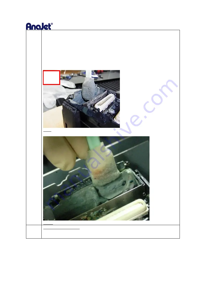
As shown in Fig. 12, Fig. 13, and Fig. 14, clean the front and back surfaces and the upper 
surface of the Wiper (rubber plate part surrounded by the yellow frame in Figure 11).


NG


Summary of Contents for Ri 1000

Page 1: ...1 For safe and correct use be sure to read the Safety Information in Safety Information and Quick Installation Guide before using the machine Version 1 2 RICOH Ri 1000 User Manual ...

Page 2: ...2 Rev Date Author Description 1 0 09 28 2018 J Manzano First Issue 1 1 10 1 2018 J Manzano Rev 1 1 1 2 10 19 2018 J Manzano Rev 1 2 ...

Page 3: ...our printers IP Address 32 Adding a new printer to AnaRIP 36 2 Preparing Media for Printing 38 2 1 Mounting Print Table onto Printer 38 2 2 Mounting Substrate onto Print Table 40 2 3 Setting the Print Table to Ready Position 42 Moving Table 43 3 Printing your image 45 4 Using AnaRip to Print Light Color Garments 50 4 1 AnaRIP Raster Image Processor 50 4 2 Printer Performance 50 4 3 AnaRIP Advanced...

Page 4: ...justing Head 93 7 2 Adjusting Table 96 7 3 Adjusting the print position 98 8 Replacing Service Parts 100 8 1 Service part 100 8 2 Maintenance Schedule 101 Daily 101 Weekly 102 How to Clean the Maintenance Unit and the Flushing box 103 How to Clean the Cover of Head Nozzle Plate the Nozzle Cover 112 Monthly 118 8 3 Preparing Your Printer for Storage Shipping 127 8 4 Using Printer in 4 color mode CM...

Page 5: ...5 ...

Page 6: ...ated by you using this machine or any results from the data executed by you Notes Read this manual carefully before you use the product and keep it handy for future reference For safe and correct use be sure to read Safety Information before using the machine The manufacturer shall not be responsible for any damage or expense that might result from the use of parts other than genuine parts from th...

Page 7: ... Machine The meanings of the safety symbols for this machine are as follows Caution Prohibition General mandatory action sign Do not touch Caution risk of having hands or arms caught Caution risk of electric shock Caution hot surface Warning Laser beam ...

Page 8: ...RICOH Ri 1000 User Manual 8 1 Before You Begin Accessory Box Contents Power cord NA 1 Ethernet cable 1 Genix Waste Bottle 1 Genix Waste tube 1 Medium Platen 1 Medium frame 1 Black Pretreated T Shirts 2 ...

Page 9: ...H Ri 1000 User Manual 9 Maintenance Supplies Cleaning Liquid 1 Cleaning Applicators 1 Lint Free Wipes 1 Heat Press Paper 1 Grease 1 Polyethylene gloves 5set Squeegee 1 Syringe Kit 1 Cleaning Fluid Set 6set ...

Page 10: ...RICOH Ri 1000 User Manual 10 W1W2KCMY Ink Set 6Set Pretreatment 64oz 1 Manual Safety Quick Installation Guide 1 User Manual 1 ...

Page 11: ...RICOH Ri 1000 User Manual 11 Printer Specifications ...

Page 12: ...RICOH Ri 1000 User Manual 12 1 2 Part Identification ...

Page 13: ...t moves left and right when printing The carriage requires regular cleaning Wiper It is a gum plate that wipes the ink off on the print head Head Cap It prevents the print head from drying Flushing Box It collects the ink discharged during the flushing operation If a message is displayed replace ...

Page 14: ...perform automatic maintenance periodically But if you do not maintenance periodically the ink in the cartridge could settle and or coagulate causing poor image quality or printer failure Some parts require periodical replacement This printer includes parts that require replacement due to usage Parts that must be replaced by a service representative If the printer encounters an error message be sur...

Page 15: ...RICOH Ri 1000 User Manual 15 1 4 Installation Space Needed for Printer Installation Space Top View Installation Space Side View Installation Space Side View ...

Page 16: ... Printer 1 Open the top cover and remove shipping bracket holding the Y axis in place by removing the 4 Philips head screws 2 Slide the waste ink tube through the cap of the waste ink tank so the black rubber o ring catches the lid of the bottle ...

Page 17: ...ve Warning The printer cannot determine if the waste ink bottle is connected please make sure the waste ink bottle is connected properly During the initial ink charge if the cover is opened it will pause the procedure To resume hold the power button down to reboot the printer 4 Connect the power cable to the back of the printer and to a functional wall outlet AC Power Connector AC Power Switch Pow...

Page 18: ...LCD screen for 3 seconds To power off hold down the power button on the front near the LCD screen for more than 3 seconds and return the I O switch to O off 7 The printer is starting to boot 8 After booting the printer will perform initial charging if the printer is not charged Initial charging takes about 15 20 minutes and the display will show a status percentage Warning During the initial ink c...

Page 19: ...le capacity level Stored Job folder Check the recent images used for printing Print directly from the stored folder or from jobs sent via network cable Choose print job from USB device SET EJECT will move the table into the print ready position table to the rear of the printer or EJECT the table to allow the media to be place onto the table STOP will stop any current movement of the table and allo...

Page 20: ...atus in detail providing print readiness Displays current ink levels in each installed cartridge Displays the status of waste ink bottle Reset counts of waste ink bottle Press the icon to initialize the waste ink bottle once waste ink tank is manually drained emptied ...

Page 21: ...ts a nozzle check pattern result Performs head cleaning automatically using systems components Allows carriage to be released cover can be opened to manually clean the printheads during maintenance or troubleshooting and the maintenance station 1 ...

Page 22: ... Prints an adjustment pattern for the print head alignment of bi directional printing Prints an adjustment pattern to table to carriage alignment Prints an adjustment pattern to determine print start position or image alignment during print ...

Page 23: ...RICOH Ri 1000 User Manual 23 Service Part Status Displays the current usage or status Green Yellow Red date of last replacement for the service parts ...

Page 24: ... 1000 User Manual 24 Settings Perform controls of ink path Network setting factory reset on off media sensor dry time temperature toggle C F High Speed mode white clean freq Display printer general information ...

Page 25: ...nstructions Printer Software Program Requirements Once the ink cartridges are installed and ink flow has been established it s time to install the AnaRIP software onto the PC Your PC must have Microsoft Windows Vista Windows 7 Windows 8 or Windows 10 operating system or on a MAC some kind of Windows emulation must be running such as Parallels or Boot Camp The computer also needs to have an ETHERNE...

Page 26: ...000 User Manual 26 Firewall Settings From the WINDOWS control panel dialogue box select WINDOWS DEFENDER FIREWALL Select the INBOUND RULES in the left frame of the dialogue Then select NEW RULE in the ACTIONS BOX ...

Page 27: ...RICOH Ri 1000 User Manual 27 Select PROGRAM and click NEXT ...

Page 28: ...RICOH Ri 1000 User Manual 28 Type the path of the program e g C Program Files x86 AnaJet AnaRIP AnaRIP exe or browse to it via the BROWSE button Select NEXT once the file path has been selected ...

Page 29: ...RICOH Ri 1000 User Manual 29 Select the ALLOW THE CONNECTION radial button and click NEXT ...

Page 30: ...RICOH Ri 1000 User Manual 30 CHECK the box of the correct PROFILE when this should be applied it is suggested to check DOMAIN and PRIVATE ...

Page 31: ...RICOH Ri 1000 User Manual 31 Name the rule and add a description optional then select FINISH when completed ...

Page 32: ...r the settings tab o C Select the IP ADDRESS option in the menu dialogue box o D Enter the STATIC IP ADDRESS the printer will be using NOTE Printer must be directly connected to a laptop desktop device via the provided ethernet cable For a DYNAMIC setup enable the DHCP as shown below to add the printer to an existing network Example ...

Page 33: ...he printer s IP address Windows Connect the provided ethernet cable to the PC s ethernet port and to the printers ethernet port For connecting directly to the printer from a PC that is not parts of a network Open the command prompt dialogue box ...

Page 34: ...e command prompt In the Ethernet Adapter Ethernet section use the IP address but change the last 3 digits to a number that will be unique to the printer and the Subnet Mask In the example below we took the XXX XXX XXX 172 and will assign 169 254 248 174 to the printer ...

Page 35: ...i 1000 User Manual 35 Enter the new IP address and the subnet mask into the printer by going to the settings tab options IP Address DHCP must be disable Select the change option and make sure DHCP is disabled ...

Page 36: ...d via the Manage Printers in the View section of theRIP View Manage Printers By default the AnaRIP software will have the Ri 1000 3000 mP5 and 6000 mP10 FILE listed as options In the MANAGE PRINTERS dialogue box select the ADD PRINTER BY ADDRESS Enter the IP ADDRESS for the printer Click CHECK to confirm the IP ADDRESS is correct ...

Page 37: ...RICOH Ri 1000 User Manual 37 Click ADD once IP ADDRESS is confirmed and correct Confirm the IP address matches the information on the printer ...

Page 38: ...RICOH Ri 1000 User Manual 38 2 Preparing Media for Printing 2 1 Mounting Print Table onto Printer The Table is mounted on the table base using magnets shown below in black ...

Page 39: ...FT or down to increase the gap between the printhead and the table for thicker substrates Turning the knob to the RIGHT or up will move the platen up towards the printhead to achieve best print quality get print table within 1 5mm of the printhead carriage For T shirts having table set to zero will allow for best results ...

Page 40: ...g flat on top of the table pull garment from the sides front and back to ensure no wrinkles are present Wrinkles may cause head strikes to occur pre press shirts prior to printing to allow for a flatter surface Note Table hoop may not fit around thicker garments Click SET with the garment as flat as possible 1st try flattening garment easiest if dressed lower table if necessary When clear Orange b...

Page 41: ... this way you should not need to adjust the table height again unless you are changing the substrate you are printing on from T shirt to sweat shirt for example For this reason when you get an obstruction message you should always try to flatten the garment to clear the obstruction before lowering the table Caution Having the head too far away from the printing surface in addition to causing poor ...

Page 42: ...o Ready Position By clicking SET it will bring the table into the printer During this process an optical lens will scan the top of the table If the obstruction detection determines an obstruction you will need to flatten the garment or lower the table slightly ...

Page 43: ...ition If the table is stops during this process the system has detected an obstruction and will need to be cleared Stop This button is used to stop the printer during movement If you press stop The screen below will show up and you will be prompted to cancel the print or continue printing ...

Page 44: ...RICOH Ri 1000 User Manual 44 Eject This button is used to return the position of the print table and prepare it for another substrate ...

Page 45: ...ction 2 3 2 Confirm the table height is correct and there are no obstructions detected 3 With the garment on the table press the SET button 4 The Status Bar will show READY in the upper left hand corner If the status bar shows anything else such as maintenance or ink error etc you will not be able to print You can print in three ways 1 Send the printable file from the PC through the ethernet port ...

Page 46: ...RICOH Ri 1000 User Manual 46 2 Selecting a job from the USB flash drive Insert USB Drive into front USB port Tap the USB icon Tap the desired file to print then select the PRINT icon ...

Page 47: ...lected print will be displayed in the thumbnail preview 3 Print from the internal memory Jobs previously sent from the PC will be stored in internal memory Tap the Stored Job Icon Tap the desired file to print then select the PRINT icon ...

Page 48: ...al 48 The selected print will be displayed in the thumbnail preview 4 To CANCEL a print job press the button during the print the following dialogue box will appear Then select the CANCEL button to stop the current print job ...

Page 49: ... SET and in the READY position the job will print once successfully transmitted from AnaRip A file that has been previously been sent directly to the printer can be retrieved from the printer s Internal Storage for reprinting Select Job from Internal Storage You can now scroll through all of the print jobs and select the file you want to ...

Page 50: ...uch more commercially acceptable print o AnaRip is able to accept many other file types including but not limited to PDF AI PSD and GIF 4 2 Printer Performance Before you start a print job you will want to make sure you have proper ink flow and print quality to assure the best results This will require that you perform a Nozzle Check possibly followed by a Print Head Clean if needed Before printin...

Page 51: ...ur images as TIFF or PNG file types The TIFF and PNG formats both support transparencies generally required for dark shirt printing and use lossless compression that will keep your file high quality It is also good practice to avoid saving images as JPG These are compressed file formats originally design for internet use only that loose quality every time they are re saved If you are using the nat...

Page 52: ...nu At the right top of the settings you will see a drop down select for View When printing a light garment you will see 3 choices Color Layer Displays the CMYK Colors that will appear on your substrate garment True View What you see is what you get WYSIWG Displays how the final result should appear when print is completed ...

Page 53: ...Textile Color Selection Change the textile color to determine if your image requires a white under base Light color garment examples are Yellow Pink Light Blue etc By changing the textile color your preview will change shown below ...

Page 54: ...THERNET is selected in the Printer Name drop down then when the print button is pressed the job will RIP to the Ri 1000 printer that is currently connected to the computer through the ethernet cable Printing this way is similar to using any standard desktop printer If Ri 1000 File is selected then the AnaRIP software will process the file to destination of your choice You can RIP your files to you...

Page 55: ... when the Ri 1000 printer is selected the Platen size will also default to MEDIUM 12 6 X 18 in This is the Platen that will be included with your printer LARGE 16 x 20 in and SMALL 10 5 x 13 in are optional Platens that can be purchased as an accessory ...

Page 56: ...oplet size resulting in less saturation ideal for thinner substrates like polyester normally should not be used as prints will be faint Disabled in AnaRip with this dot size o Wide Must be used with UNI DIRECTIONAL enabled provides a slightly larger droplet size than Narrow Disabled in AnaRip with this dot size o Extra Wide This is the default that should be used for most prints Number of Copies i...

Page 57: ...ag the corners the aspect ratio will be maintained If you drag the tops or sides you will stretch or compress your image Position is for placement of your graphic into a specific area of the Print Table This will be used to move a graphic higher or lower vertically or left to right horizontally The image can also be moved by dragging the image with your mouse in the preview screen If you want to c...

Page 58: ...r PowerBright Plus to convert from the PCS into the native color space of the Ri 1000 ICC Input Profile Images created in Photoshop most often contain a built a profile for the specific color space the image was designed in The rip allows you to change use a different ICC profile instead of the ICC profile that is part of the image file It is recommended to use Profile from image in most print cas...

Page 59: ...aturation The printer substitutes the nearest color that it can print for out of range colors and adjusts in range colors to make them more vivid o Relative Colorimetric The printer substitutes the nearest color that it can print for out of range colors in range colors are not adjusted o Absolute Colorimetric The printer substitutes the nearest color that it can print for out of range colors and t...

Page 60: ...RICOH Ri 1000 User Manual 60 Brightness Adjustment Brightness Up Brightness Down Contrast Adjustment Contrast Up Contrast Down Saturation Adjustment Saturation Up Saturation Down ...

Page 61: ...k set if using superfine as mentioned you will have to change the inkset to Superfine NOTE the superfine ink set will not yield good results if used with the quality setting FINE or SPEED the results will be too faint Ink Set Profile Management To add an additional Ink Set select the Plus sign and proceed to fill in the ink set editor ...

Page 62: ...ted through the use of X Rite IProfiler or other similar products ICC Color Profiles Manage Color Linearization Curves To add a new linearization curve click on the plus icon and locate the location of the file on the PC AnaRIP comes with a curve editor preinstalled The curve editor can be located in the Start Menu of the PC Note The default profiles do not require linearization curves ...

Page 63: ...able ICC preview within the AnaRIP this is modifying the current screen settings on your computer to display our color profile used for the output of our AnaRIP color profile This function will not change the output of the printer It will help you see the true color profile rather than the preselected color profile on your monitor This feature will help achieve color accuracy once you start your p...

Page 64: ...RICOH Ri 1000 User Manual 64 Selecting ICC Preview ...

Page 65: ...removed Do not let the shirt fold or touch itself as this could cause ink transfer to other parts of the garment Take the garment to your heat press or conveyer dryer fix the ink to the garment When removing the fabric be careful so that your hand or any other part of your body does not come in contact with ink If your skin comes in contact with ink wash the affected area thoroughly with soap and ...

Page 66: ...diately SoftTouch heat press paper can be reused several times Instead of SoftTouch a Teflon sheet or Kraft Paper Cover Sheet can be used When reusing the SoftTouch Paper make sure there are no wrinkles as these will transfer to the garment If this is the case use a new sheet The printed garment is now completed If you are also printing dark shirt images you need to reduce the heat press temperatu...

Page 67: ... Pre treatment Liquid is to be used with care Do not let it contact your eyes Do not breathe in the vapor or mist Thoroughly wash your hands after handling it If your clothing gets contaminated wash it before reuse If an accident happens please follow the Caution and First Aid instructions on the Pre treatment Liquid bottle label Due to the corrosive nature of the pre treatment solution we recomme...

Page 68: ...r adequately and aneven amount achieving an even wet sheen Remember you only need to apply the pre treatment to the areas that will be printed on Squeegee the pretreatment in one direction to help spread the pre treatment evenly after spraying This also flattens any fabric fibers that may have risen due to the application of the wet pre treatment Dry the substrate You can achieve an excellent resu...

Page 69: ...s highly dependent on proper application of pre treatment Poor Pre Treatment Can Be Seen on the Left Side of this Image and is shown to be muddled gray and not as solid as the nose of the leopard green arrow Check the Enable White Underbase box to use white underbase layer in the print ...

Page 70: ...ent Preview Color selected Select the Underbase layer in the view section where True View is displayed by default Most cases can use Fine Extra Wide for underbase Speed should be used to check print position Super Fine should be used for special applications that require a lot of ink Not available in AnaaRip 5 2 will be added soon View After Enabling White Ink ...

Page 71: ...sed checkbox will be checked will only use white ink where required in the image grayscale effect Quality is set to Fine The Variable Dot Range will be set to Extra Wide The Bi directional Underbase printing checkbox will be checked for optimum speed when printing the Underbase ...

Page 72: ...sed in the color pass o Note when using the content based unchecked it is highly recommended to also add a color layer wait time dry time in between the white underbase and the color layer o In the printer tab o Tap the icon o Tap icon o Insert a numeric value in seconds based on how saturated the white under base is ...

Page 73: ...ur printing results by selecting the Underbase and TrueView option The Underbase and TrueView images should now be visible in the preview screen There are five ways to adjust your white Underbase Color Contrast Opacity Contrast Choke Individual Color Adjustments and Pure White Note that some of the functions are disabled when Content Based is not checked ...

Page 74: ...ed with the Color Contrast slider bar Moving the Brightness slider bar all the way to the right to 100 with give you a more solid white ink Underbase and in turn brighter colors Moving the slider bar left towards 100 will create more of a grey scale white Underbase and less vivid colors Color Contrast Slider Up Color Contrast Slider Down ...

Page 75: ...en your image has a soft or semi transparent edge or the image has semi transparent colors in it Movingthe slider bar to the left will reduce the amount of white Underbase beneath these areas to help create a smoother blend Opacity Contrast Up Opacity Contrast Down ...

Page 76: ...of the Underbase so that white ink does not appear outside the prints edges of the final color pass Under the Choke setting use the default value of 2 on a full size print you will lower this if your image is small If you see any white around the edges of your final print you will want to increase the choke value Choke Needed If you are printing an image that is only white you will need to set the...

Page 77: ...is drop down menu you are able to increase or decrease the amount of white ink Underbase that will print under that color This will help you bump up or bring down certain colors in your final print You can multiple different colors using this setting Color Adjusted Up Color Adjusted Down ...

Page 78: ...ure White Adjustment Remember you can still further adjust your image by changing the settings on the Color Adjustments Tab Also located on that tab is the Transparency window that will let you remove a color range from your image to create a transparency This feature is limited so you may achieve better results using your image editing software Enable White Highlight ...

Page 79: ...re there is dead pixel space between any large amounts of pure white and any CMYK color as it may cause white ink to mix the color at the edge To remove all of a specific color range select Select Color Then click the color you want to remove from your image The selected color will be removed from the entire image You can increase the range of the color removed by adjusting the Color Tolerance sli...

Page 80: ... completed your settings and adjustments you can now send your image to the printer by pressing Print or save the graphic to your computer or an USB drive by selecting Print to file The Printer will first print the White layer Once completed the printer will print the Color Pass Since the white Underbase layer may not be dry enough to receive the color layer there is an adjustment on the printer s...

Page 81: ...ing a heat press Re open the heat press and cover the image with SoftTouch heat press paper Instead of SoftTouch a Teflon sheet or a Kraft Paper Cover Sheet can be used If you use a Teflon pad it will leave a semi glossy look to the prints Close the heat press and let the ink cure for the prescribed time Figure 7 6 1 When the time is completed open the heat press remove the heat press paper and yo...

Page 82: ...tion Every 3 hours White channel cleaning Every 12 hours All channel cleaning Alarm agitating white cartridge Every 7days Alarm manual cleaning WARNING Auto maintenance will be not be perform if the following conditions occur Failure to perform Auto maintenance can result in a clogged print head Printer is powered off Always keep the printer powered on Ink cartridge is missing or reading 0 CR enco...

Page 83: ...og is removed and reflected on the nozzle check Nozzle checks must be performed on transparent overhead projector film If any part of the transparent overhead projector film is curled tape it down to avoid an obstruction detection The MEDIUM sized platen included with the printer optional small and large tables available must be used to perform the nozzle check ...

Page 84: ...ocated in the tab Check the results of the printed nozzle check pattern In your nozzle check please check for the following and take the appropriate steps Perfect Nozzle Check Nozzle Deflection When horizontal lines are uneven __ Clogged Nozzle When the horizontal lines have small or minor gaps ...

Page 85: ...g nozzles Use STRONG when there are large missing nozzles in the nozzle check If missing nozzles persist after performing the normal or strong cleans let the printer sit idle overnight 6 hrs SELECTED NOT SELECTED After performing the normal cleaning nozzle condition is not recovered proceed to using the STONG clean option Warning STRONG head cleans will use more ink than the NORMAL cleans use only...

Page 86: ...erform a white head clean depending on the need for the use of white ink on an upcoming job in queue Below is a description of the clean levels LOW L1 After 20 CMYK Prints Clean White L2 After 15 CMYK Prints Clean White Default L3 After 10 CMYK Prints Clean White L4 After 5 CMYK Prints Clean White HIGH L5 After 1 CMYK Print Clean White ...

Page 87: ... the cover of the printer to allow for better visibility of the print head carriage Using a large cleaning applicator wipe the printheads in one direction from back to front DO NOT SCRUB the printhead DO NOT reuse the same large cleaning applicator for a new printhead To remove stubborn clogged nozzles of the print head gently wipe the nozzle surface of print head using swab with RICOH cleaning so...

Page 88: ...RICOH Ri 1000 User Manual 88 clean the gaskets and wiper mechanism If the manual cleaning is finished press END button to return to the previous menu and to return the carriage to its home position ...

Page 89: ...kage DO NOT excessively agitate swing as it may cause ink leakage MUST AGITATE SWING as instructed using the swing method Other methods may cause ink leakage Hold the cartridge horizontally as shown in Fig 1 Shake the ink cartridge for 100 seconds reciprocally while keeping it horizontal in the direction of the arrow in Fig 1 The swinging speed is a speed at which a length of 30 cm is reciprocated...

Page 90: ...RICOH Ri 1000 User Manual 90 After agitating cartridges insert the cartridges ...

Page 91: ...ttle Once a certain amount of ink has been used the following message is displayed on the touch panel Put the waste ink form the waste ink bottle into a container to discharge it You can check the amount of waste ink on the Status Panel and reset the waste ink counter To reset the waste ink counter after the waste ink tank has been emptied press WASTE INK RESET button Warning Do not reset the wast...

Page 92: ...is not good this process need to perform These functions can be performed on the tab You can print the basic adjustment pattern Also it s better to print it on the transparent A4 media such as OHP films And it is recommended using medium sized platen If a part of the media is raised use tape to fix the four corners of the media Then press the set button to send the table into print ready position ...

Page 93: ...nt is fuzy this adjustment may impro ve the result NOTE Always check the table height 1st The reading on the dial should be close 0 i n most cases If the printing surface is too far away from the head the prints will be fuzzy and the lines may not appear straight Press the button the pattern of adjusting head is printed After find an appropriate adjustment value form the print result of adjustment...

Page 94: ...e test pattern B C etc When there are no straight vertical side lines like upper illustration check the last square out of the sequence of squares with the smallest gap in side lines and find a corresponding value As upper illustration the value is 4 After you have entered a value for all the rows press the ALIGN button which sets the new values Reprint the pattern and repeat the above process Rep...

Page 95: ...RICOH Ri 1000 User Manual 95 ...

Page 96: ...ozzle deflection and the table height is correct you need to do this function Press the button of print position Find an appropriate adjustment value from the print result of adjustment patterns Find a pattern with a square in the lightest color and horizontal lines on both sides aligned A value on the upper of the pattern indicates an appropriate adjustment value An appropriate adjustment value i...

Page 97: ...es for 2 and 6 are misaligned in the same direction but the horizontal lines for 14 are misaligned in the opposite direction In this case a value that horizontal lines align exists somewhere in between 6 and 14 Afte r passing the value the horizontal lines begin to be misaligned in the opposite direction as gettin g closer to 14 By referring to the alignment of the lines decide a value between 6 a...

Page 98: ...r printing the pattern for the print position adjustment you have to find appropriate value Position the paper so that the cross on the test print paper comes at the right bottom corner Values can be selected between 4 0 4 0 in increments of 0 1mm To move the print position to the A direction input a value between 1 and 4 in the Tabl e input area To move the print position to the B direction input...

Page 99: ...position to the C direction input a value between 1 and 4 IN the tabl e input area To move the print position to the D direction input a value between 1 and 4 IN the Hea d input area After entering the values press the align button to set the values ...

Page 100: ...to be changed as discussed below Each icon will provide the status of each service part When a component is selected the replacement dialogue box is displayed It shows the count and the date last replaced The color of each component will be displayed in Green or Yellow and Red Green is normal Yellow replace soon Red requires replacement ...

Page 101: ... cartridge damage ink leakage DO NOT excessively agitate swing as it may cause ink leakage MUST AGITATE SWING as instructed using the swing method Other methods may cause ink leakage Hold the cartridge horizontally as shown in Fig 1 Shake the ink cartridge for 100 seconds reciprocally while keeping it horizontal in the direction of the arrow in Fig 1 The swinging speed is a speed at which a length...

Page 102: ... 7 days When prompted you should perform Clean the maintenance unit Clean around the heads Clean the encoder depends on use 1 time a month is OK unless using 5 days a week 7 to 8 hours a day Grease the guide rails depends on use 1 time a month is OK unless using 5 days a week 7 to 8 hours a day ...

Page 103: ...it depends on the degree of contamination it is a standard to use about 5 to 10 in a series of cleaning work CAUTION DO NOT rub too strongly DO NOT wipe other than the areas indicated there is a possibility that parts may be damaged deformed or detached If parts breakage deformation or detachment occurs it may cause a machine failure Cleaning time About 10 minutes Things to prepare Gloves commerci...

Page 104: ...ning the Moisturizing Cap The Moisturizing Caps three pieces in Fig 1 gently wipes off the top part the side part and the inner part of the cap schematic diagram shown in Fig 2 CAUTION DO NOT to deform or scratch caps Deformation and scratches may cause troubles Especially wipe the top part gently and carefully Fig 1 Fig 2 Step 4 Fig 3 shows an example of how to apply the Cleaning Applicator ...

Page 105: ...ully so as not to shift or detach this part Be sure to return the parts when the parts in the cap are displaced or removed Press down until the spring bottoms out If not returned properly it may cause nozzle out See Fig 4 and Fig 5 for the figures before and after cleaning For parts inside the Suction Cap it is sufficient that the solid ink or the stuck ink is removed Step 7 Cleaning the Wiper and...

Page 106: ...ide parts of the Wiper Cleaner Fig 8 Clean the area indicated by the red frame and the surface of the Lever indicated by the green frame in Figure 8 Be careful as the lever is thin easily deformed broken and detached Clean the lever to the surface of the green frame and wipe it gently ...

Page 107: ... may easily deformed broken and detached For example in Fig 9 the Cleaning Applicator is put too deeply and it is NG An example of work is shown in FIG 10 Fig 9 Fig 10 Step 9 3 Cleaning of the Wiper As shown in Fig 12 Fig 13 and Fig 14 clean the front and back surfaces and the upper surface of the Wiper rubber plate part surrounded by the yellow frame in Figure 11 NG ...

Page 108: ...RICOH Ri 1000 User Manual 108 Fig 11 Fig 12 Fig 13 ...

Page 109: ...hown in Fig 15 rotate the roller move the Cleaning Applicator back and forth and wipe the entire circumference Fig 15 Fig 16 and 17 show the state after cleaning of the Wiper and the Wiper Cleaner described above To remove dirt to this level the Roller Roller of wiper cleaner ...

Page 110: ... Step 11 Cleaning the Flushing box If the top of the Flushing box is dirty with ink clean it with a clean stick as shown in Fig 18 After wiping off do not leave convex ink on the top of the Flushing box The part indicated by the red circle in Fig 18 is fragile so wipe gently ...

Page 111: ...er Step 14 Press the END button The carriage moves to the right end and the Head is capped Step 15 After completion of cleaning perform AUTO HEAD CLEANING Recommendation It prevents the ink from drying out and clogging the nozzles After completion it is recommended to print the Nozzle Check and check that the ink discharge is normal The Flushing box ...

Page 112: ...solid ink lint etc that stuck to the Nozzle Cover Cleaning must be done with a dedicated cleaning kit Cleaning time About 15 minutes Things to prepare Gloves commercial product one that does not pass ink To wear Protective glasses or goggles commercially available To wear Cleaning Applicator dedicated to Ri 1000 Cleaning Liquid dedicated to Ri 1000 Cleaning procedure Contents Step 2 Press the MANU...

Page 113: ...d the Cleaning Liquid Immerse the Cleaning Liquid into the Cleaning Applicator large For cleaning use the Cleaning Applicator containing the Cleaning Liquid and the Cleaning Applicator not containing the Cleaning Liquid CAUTION Be sure to use Cleaning Applicator and Cleaning Liquid dedicated to Ri 1000 Otherwise it may cause a failure Step 6 Look at the bottom of the Head and clean the Nozzle Cove...

Page 114: ...e cover surface Clean the surface of the specified area of the Nozzle Cover with the Cleaning Applicator containing the Cleaning Liquid As shown in the figure below clean along the arrow direction Do not clean the nozzle side cover with a wet cleaning applicator ...

Page 115: ...on of the Nozzle surface and the Nozzle Cover After cleaning and if washing the Cleaning Liquid and foam etc attached to surplus have adhered to the Head wipe it off with the dry cleaning Applicator that does not contain the Cleaning Liquid it is important not to leave wet cleaning fluid on any part of the head after this manual clean Head part side part Clean the side of the Nozzle Cover with the...

Page 116: ... not wipe the protrusion of the Nozzle Cover downward as shown below The Nozzle Cover may come off causing failure Reference Cleaned the Nozzle Cover Step 7 Clean the left and right ribs on both ends of the carriage Step 8 After cleaning the Nozzle Cover remove the tray or paper placed under the Head Step 9 Close the Front Cover Step 10 Press the END button The carriage moves to the right end and ...

Page 117: ...7 Step 12 After completion of cleaning perform AUTO HEAD CLEANING It prevents the ink from drying out and clogging the Nozzles After completion it is recommended to print the Nozzle Check and check that the ink discharge is normal ...

Page 118: ...age Apply grease to the Guide Rod and clean the Encoder Sheet with Cleaning Liquid Cleaning work should be carried out until completion without interruption Also sure to use Cleaning Applicator and Cleaning Liquid dedicated to Ri 1000 Otherwise it may cause a failure Cleaning time Half an hour Things to prepare Gloves commercial product one that does not pass ink To wear Protective glasses or gogg...

Page 119: ...iage moves to the center position Step 2 Open the Front Cover Step 3 Wipe off the old grease and lint stuck on the guide rod with a cleaning applicator There are two guide rods guide rod front and guide rod main To clean both two Caution When cleaning the guide rods try to avoid touching the encoder The guide rod main The guide rod front Cleaning applicator ...

Page 120: ...orrect grease and the accumulation of lint can cause the carriage to malfunction and need to be replaced if the guide rods are not cleaned and greased correctly Step 7 As shown in Fig 1 The Guide Rod main Apply approximately 0 01 ml of grease to each of the six peripheral parts of the arrow The Guide Rod front The six peripheral parts of the arrow After putting grease apply it to the full range of...

Page 121: ... rod At putting After applying 0 01 0 02ml height 2mm Circumferential grease application range Use a dedicated Cleaning Applicator to spread the grease smoothly on the top portion of the rod cover about the top third of the circumference of the rod Grease the top of the rod in this area ...

Page 122: ... to adhere to the carriage Belt Do not allow grease to adhere to the carriage Step 8 Move the carriage to the left and right by hand to smooth the grease Move the carriage slowly over 2 seconds within the designated sliding range and move it more than two round trips Carriage Belt Guide Rod Main Encoder ...

Page 123: ...cleaning position when the carriage is moved to above the Maintenance Unit the Wiper interferes with the Head it may damage the Head Step 9 Wipe away grease that protrudes far beyond the coverage of Fig 1 2 and 3 Also confirm that grease is not attached to the Filler Sensor Step 10 Clean the Encoder Sheet after applying grease to the Guide Rod Move the carriage to the left end side by hand Feeler ...

Page 124: ...ering to the Encoder Sheet Move the carriage to clean the entire Encoder Sheet CAUTION Be sure to clean in the direction of the arrow in the figure Do not directly touch the encoder seat with hands Do not bend the encoder seat Do not allow the Cleaning Liquid to adhere to the timing belt Do not allow the Lint Free Wipes to come into contact with the Guide Rod Encoder Strip ...

Page 125: ... to the left end by hand The Wiper may hurt the Head if it makes it stand by on the right end Maintenance Unit Step 14 Close the Front Cover Step 15 Press the END button The carriage moves to the right end and the Head is capped Step 16 After completion of cleaning perform AUTO HEAD CLEANING Recommendation It prevents the ink from drying out and clogging the nozzles ...

Page 126: ...RICOH Ri 1000 User Manual 126 After completion it is recommended to print the Nozzle Check and check that the ink discharge is normal ...

Page 127: ...ng Your Printer for Storage Shipping Note Please have cleaning cartridges available for all channels Remove Ink Cartridges Insert Cleaning Cartridges Go to tab Select Select Confirm by selecting YES to charge the system with cleaning solution ...

Page 128: ...y to use CMYK and keep the white in a storage mode 1 Insert the Cleaning cartridges designated for W1 and W2 channels 2 Select INK PATH CONTROL from the SETTING tab 3 Select CLEANER CHARGING 4 Select WHITE ONLY PLEASE ALLOW UP TO 40 MINS APPROX FOR THE SYSTEM TO FLUSH THE INK OUT AND FILL THE WHITE LINES WITH CLEANING SOLUTION ...

Page 129: ...ng underbase All kinds all printing Color ink in color channel Cleaner in white channel 4 color mode After ink without white state White media OK for any printing that does not require a white under base The Cleaner in white channel is for protect the nozzle of print head Cleaner in all channels After cleaner charging state unprintable For long term storage Shipping 10 ...

Page 130: ...ng Firmware 1 Download the application from www anajet com downloads 2 Open the Printer Manager Application 3 Enter the printer IP address needing to be updated 4 Select the version to use for the update 5 Click the F W Update button then select START UPDATE to send the firmware update Note always update the Interface Board first prior to any firmware updates ...

Page 131: ...RICOH Ri 1000 User Manual 131 6 Wait for the notification that the firmware update delivery is complete 7 Click OK on your printer s screen to continue the update ...

Page 132: ...RICOH Ri 1000 User Manual 132 8 Click the install option on the screen to continue ...

Page 133: ...RICOH Ri 1000 User Manual 133 9 Then select open 10 Wait for the update to complete then restart the printer as instructed by pressing the yes button ...

Page 134: ...RICOH Ri 1000 User Manual 134 ...

Page 135: ...RICOH Ri 1000 User Manual 135 Go to the information section in the settings tab Verify the Firmware version matches the one installed ...

Page 136: ...RICOH Ri 1000 User Manual 136 9 2 Collecting Log Files from Printer Unzip the logcat package Run the GNX317W logcat exe software Enter the printer s designated IP address and press extract ...

Page 137: ...RICOH Ri 1000 User Manual 137 Select where you would like to save the logs and the desired name of the zip package to be created Once the logs have been downloaded press OK ...

Page 138: ...cations and to alter it and redistribute it freely subject to the following restrictions 1 The origin of this software must not be misrepresented you must not claim that you wrote the original software If you use this software in a product an acknowledgment in the product documentation would be appreciated but is not required 2 Altered source versions must be plainly marked as such and must not be...

Page 139: ...hirt with a white under base poor pretreat Not enough pretreat can make the white can CMYK areas of print to appear dull or fuzzy Especially if a section of the print appears sharp and another section appears dull or fuzzy See section 5 user manual Head alignment is off Perform head alignment procedure see section 7 1 make sure to rule out the above reasons before this adjustment 2 Horizontal band...

Page 140: ...ull White nozzles 100 or near 100 In adequate amount of pretreat on shirt this can cause the white ink to mostly sink into the shirt Increase the amount of pretreat being sprayed on the shirt White nozzles 100 or near 100 but look dull White ink has settled If the white cartridges have not been agitated per instructions will need to agitate the white ink cartridges for 2 minutes Then perform 3 to ...

Page 141: ...RICOH Ri 1000 User Manual 141 ...

Reviews: