Ricoh fax4700l, Service Manual
The Ricoh fax4700l is a reliable fax machine that offers high-quality performance for your office communication needs. For troubleshooting and maintenance, you can easily access the Service Manual for free download from manualshive.com. This manual provides detailed instructions to ensure your fax machine operates efficiently.
Share
Download


Reviews:
No comments
Related manuals for fax4700l

Triple Crown
Brand: A&A Global Industries Pages: 16
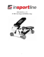
IN 9100
Brand: Insportline Pages: 9

RootsScrub B6050
Brand: ROOTS Pages: 22

LAVINA ELITE L13GE
Brand: Superabrasive Pages: 27

Vantage 14
Brand: Clarke Pages: 76

LAVINA ELITE Series
Brand: Superabrasive Pages: 48

040-X3000
Brand: Rustibus Pages: 31

1888 Foot-Bar Set of attachments
Brand: Singer Pages: 20

MAXIM 4200
Brand: American Games Pages: 16

NOVAMATIC NM 2830
Brand: FUST Pages: 49

HZL-T100
Brand: JUKI Pages: 28

DU-1181N
Brand: JUKI Pages: 100

KX-F2510NZ
Brand: Panasonic Pages: 68

KX-F2581NZ
Brand: Panasonic Pages: 82

KX-F2581AL
Brand: Panasonic Pages: 84

KX-F3000
Brand: Panasonic Pages: 96

KX-F220
Brand: Panasonic Pages: 132

KX-F2681BX
Brand: Panasonic Pages: 146


