background image

RT-500-M


RHOTHETA  

Page 87 of 168 

User Manual 

o

  Confirm the changed value with “OK” or press “ESC” to leave the dialog without changing the 

previous value. 


7.4.2.5 Distance 

Unit 

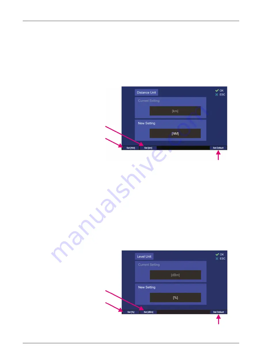
The indicating of distances can be either in kilometers [km] or in nautical miles [NM]. The default value 
is “[km]”. 
To change the indication of the distance unit, press either the “OK” or “Edit value” while the setting is 
marked by the green frame. 


Choosing the kilometers as the 

distance indication unit 


Choosing the nautical miles as the 

distance indication unit 


Choosing the default setting for the distance indication 

(kilometers) 

Figure 91. Changing the distance unit 

o

  Press the hotkey “Set [NM]” to set the distance unit to “[NM]” (Nautical Miles). Each distance 

indication in the application will be indicated in nautical miles. 

o

  Pressing the hotkey “Set [km]” will set the distance unit to “[km]” (kilometers). Each distance 

indication in the application will be indicated in kilometers. 

o

  Press the hotkey “Set Default” to set the distance indication to the default value (kilometers). 

o

  Confirm the changed value with “OK” or press “ESC” to leave the dialog without changing the 

previous setting. 

7.4.2.6   Level Unit 

Indicating of levels (like signal level, or squelch level) can be either in “[%]” or in “[dB]”. 
To change the currently chosen unit for the levels indication press either the button “OK” or “Edit 
Value”, during the setting “Level Unit” is marked. 


Choosing dBm as level indication 

unit 


Choosing percent as level indication 

unit 


Choosing the default setting for level indication (%) 

Figure 92. Changing the level unit 

Summary of Contents for RT-500-M

Page 1: ...User Manual RT 500 M ...

Page 2: ... 4879 15 Internet www rhotheta de E Mail email rhotheta de Copyright RHOTHETA Elektronik GmbH All rights reserved Issue 2020 03 27 Rev 1 07 Document ID 12 9 1 0002 3 1 64 Valid for RT 500 M systems with revision Rev 4 08 or higher Note The manufacturer reserves the right to make modifications to the product described here at any time and without previous information ...

Page 3: ... 37 7 1 5 Function Clear 38 7 1 6 Function Autoset Squelch 38 7 2 Scan Page 39 7 2 1 COSPAS SARSAT Scan 41 7 2 2 Monitoring 43 7 2 3 Fast Channel Scan Licensed Option 49 7 2 4 Marine Scan 54 7 2 5 SAR Scan 57 7 2 6 Scan List 63 7 3 Decode Page 67 7 3 1 Selecting a COSPAS SARSAT frequency 69 7 3 2 COSPAS SARSAT List View 69 7 3 3 COSPAS SARSAT Bearing View 70 7 3 4 COSPAS SARSAT Bearing and List 71...

Page 4: ...sition 153 9 Technical Data 154 9 1 Electrical Characteristics 154 9 2 Mechanical Characteristics 156 9 2 1 Mechanical Data 156 9 2 2 DCU Mounting Cutout 157 9 2 3 AU Mast Flange 157 10 Disposal within the European Union 158 11 Disposal outside the European Union 158 12 Maintenance and Cleaning 159 12 1 Maintenance 159 12 2 Cleaning 159 13 Appendix 160 13 1 Error Messages 160 13 2 Warnings 160 13 ...

Page 5: ...n For any questions regarding these safety instructions RHOTHETA Elektronik GmbH can be contacted at any time The observance of the safety instructions will help to prevent personal injury or damage caused by all kinds of dangers This requires that the following safety instructions must be read carefully and understood before using the product as well as observed while using the product Other addi...

Page 6: ...ironmental conditions heat humidity wind load etc that exceed the specified conditions in the manuals x Use only the manufacturer s prescribed components and or use only recommended materials and do not change them Any other use or unauthorized modifications to the product will void the authorization to operate it x Connect only approved accessories kits or additional equipment x Ensure that the c...

Page 7: ...lation This equipment generates uses and can radiate radio frequency energy and if not installed and used in accordance with the instructions may cause harmful interference to radio communications However there is no guarantee that interference will not occur in a particular installation If this equipment does cause harmful interference to radio or television reception which can be determined by t...

Page 8: ...ésent appareil est conforme aux CNR d Industrie Canada applicables aux appareils radio exempts de licence L exploitation est autorisée aux deux conditions suivantes 1 l appareil ne doit pas produire de brouillage et 2 l utilisateur de l appareil doit accepter tout brouillage radioélectrique subi même si le brouillage est susceptible d en compromettre le fonctionnement A radio license must be obtai...

Page 9: ...nction of the RT 500 M The fine frequency steps 5 kHz allow discovering hidden transmitters in the marine band and in the additional UHF band RT 500 M Frequency Range Standard Range Optional Extended Range VHF emergency band VHF marine band1 UHF emergency band COSPAS SARSAT UHF FM band 118 000 124 000 MHz 154 000 163 000 MHz 240 000 246 000 MHz 400 000 406 092 MHz 406 100 410 000 MHz F1 VHF air ba...

Page 10: ...e found under 8 8 Figure 1 General connection schematic 3 Any additional devices like external speaker compass etc can be also connected to the DCU For further information about the installation of the system please refer to chapter 8 4 Push the ON OFF button 5 When the DCU is turned on the ON OFF button lights green and the DCU indicates the loading screen s Figure 2 Figure 2 Loading screen ...

Page 11: ... This is the first page that is displayed when the system is started for the first time The next time the device is restarted the last page that was used before the restart will be loaded after the start screen To turn off the DCU hold the ON OFF button pressed for about 2 3 seconds Figure 4 Start page bearing page 7 Adjust the needed main bearing frequency the default frequency after first system...

Page 12: ...rmitted frequency ranges o Press the Swap hotkey s field D Figure 5 to set the new frequency to main bearing frequency Active Figure 6 New frequency Input o To input a maritime channel number push the hotkey Channel s field E Figure 6 and proceed by typing the number and pressing OK o To select a desired Cospas Sarsat frequency channel ABC channel RS from a drop down menu press the CP SS hotkey s ...

Page 13: ...wn in one percent steps and show the current value Figure 7 Squelch level adjustment o By pressing the Autoset SQL hotkey s field G Figure 7 the level of the squelch can be automatically adjusted to a suitable value for the current signal level For more information on the setting of squelch please refer to chapter 7 5 3 After all settings the system operates at the entered frequency ...

Page 14: ...n down to a defined value configurable in the Setup page s 7 4 2 8 but the system continues monitoring the corresponding emergency frequency The display will be turned on again if an event occurs e g signal level rises above squelch level alarm occurs scan algorithm finds an active frequency Pressing any button will return the system from standby to normal operation mode the function of the presse...

Page 15: ...f the current page or dialog Hotkeys for activating variable functions The assignment of the keys differs depending on the page or dialog Sensor of brightness Measures the ambient brightness to automatically adjust the brightness of the TFT display status keys labeled Keys in the Adjust Brightness dialog and buttons legends Returns one step back in a menu or leaves a dialogue or an adjusting field...

Page 16: ...ecting to input use either RS232 Rx or RS422 Rx not both For more information s 8 4 AU Antenna connector Connection between DCU and AU via cable For more information s 8 3 Screw Cover Waterproof protection cover for USB connector and replaceable fuses Opening of the screw cover should be done in a dry room to prevent the ingress of moisture into the interior of the DCU POWER IO Source connector x ...

Page 17: ...Waterproof internal speaker USB Only Service USB 2 0 port Used only for service manufacturing purposes For more information s 8 6 Pressure Compensation Element Equipped with a Gore Tex membrane the pressure compensation element prevents over and underpressure in the DCU Fuses Replaceable fuses F1 T3A 127V Littelfuse 154003 T F2 T5A 127V Littelfuse 154005 T F3 T1A 127V Littelfuse 154001 T F4 T0 5A ...

Page 18: ...e listed on the top line of the screen and the active page is highlighted in light blue Switching between pages is done via the corresponding navigation keys which are located directly above the page names s field A Figure 10 The top line of the screen is the same for all pages except the Setup page which contains all the necessary system setup options The hotkeys differ from page to page to provi...

Page 19: ...witching between pages Bearing Scan Decode and Setup Frequency indication Section for frequency channel indication during bearing and scanning The active frequency is displayed in white color If the scanning function is activated the currently active frequency or channel is displayed in green and the other frequencies monitored by the scanning algorithm are displayed in gray If the Repeat hotkey s...

Page 20: ...c squelch level adjustment for the active frequency for further information s 7 1 6 Escape button Pressing this button while a dialog is open will close the dialog without saving changes If no dialog is open pressing this button will go back to the last activated page The Bearing page is the end point Pressing this button on the Bearing page will have no effect when no dialog is open Monitoring sc...

Page 21: ...nt If there is no valid heading data available the symbol stays blue and crossed out This indicator shows whether there is valid position data from an external GPS available or not If there is no valid position data available the symbol stays blue and crossed out If there is valid position data the symbol turns green Indication of signal level Current signal level bar graph o Color blue means that...

Page 22: ...the bearing signal has disappeared The clock counts the time elapsed since the signal was lost The indication is in hh mm ss o Distance from the current GPS position to the stored GPS position is shown in the uppermost line of the digital bearing display This information is only indicated if GPS data is available and at least one GPS arrow is displayed MOB or Decode mode If there is more than one ...

Page 23: ... gray arrow For more information s 7 3 Bearing arrow The bearing arrow is the graphical indication of the bearing value on the 360 display The bearing arrow additionally displays the opposite direction on the compass rose The bearing value can be indicated s also o Relative to the heading of the vessel This is the case if no external compass is used o Relative to the magnetic north pole o Relative...

Page 24: ...terface If using the heading of the ship as the reference direction no compass data available the bearing will be shown on top of the 360 display If using one of the North Pole directions it will be shown on the 360 display with additional indication of the cardinal points Distance from the current GPS position to the stored GPS position 12 05 km only displayed if GPS data available Calculated GPS...

Page 25: ...ncy signal occurs or an error is detected or operating parameters exceed their specified limits the system will inform the operator by activating an alarm error or warning indication While a signal is being received signal level squelch level it is examined in the background to determine if it is a modulated emergency signal The emergency signals ELT Emergency Locator Transmitter PLB Personal Loca...

Page 26: ...ed yet but it is recommended to check the system in order to prevent damages Table 6 Alarms Errors Warnings 7 1 2 2 Frequency Channel Input Dialog The frequency input dialog is called up by pressing the hotkey Freq Ch s Figure 11 position 4 while the Bearing page is active The frequency input dialog appears in three variants with different input dialogs for o Frequencies s Input of Frequencies pag...

Page 27: ...nput field for new frequency channel If the input of the frequency channel is complete and valid pressing this button saves the new value as standby frequency channel If the input is not correct the system informs about it with following warnings o This indication appears for marine band frequencies when the entered frequency is not in the typical grid step width but is still valid o This indicati...

Page 28: ...equency for a duplex channel CP SS This hotkey opens the dialog variant for selecting Cospas Sarsat frequency group s Selecting Cospas Sarsat Frequency Groups page 33 Table 7 Frequency input dialog List of elements 1 Input of Frequencies In the frequency input dialog two ways of entering a new frequency are possible 1 input using the numeric buttons and 2 input using the arrow buttons The Frequenc...

Page 29: ...r digit values that are already set the system allows the selection of only correct numbers for the current digit Note If the system does not allow entering the desired number for a current digit control other digits in the input field and correct them if necessary The system shows you which digit is wrong by flashing the cursor frame in red Note Frequency step width depends on the selected freque...

Page 30: ... hotkey again the frequencies will change places back o Pressing the CP SS hotkey s Figure 14 position 2 opens the dialog variant for selecting Cospas Sarsat frequency groups description s page 33 o Pressing the ESC button s Figure 14 position 4 closes the dialog without saving changes o Pressing HOME button s Figure 14 position 5 closes the dialog without saving changes and leads to the bearing p...

Page 31: ...ncy with squelch standby frequency with squelch For Cospas Sarsat frequencies the squelch is set to Auto by default For more information about squelch s chapter 7 5 3 2 Input of Channels Generally channel input works the same way as frequency input the input dialog is divided into a section for the active channel and a section for the new channel s Figure 16 fields A and B With the swap function t...

Page 32: ... when channel input is complete Switching from Frequency input to Channel input dialog variant when the Standby frequency does not belong to marine band will show the empty Standby field and a warning s Figure 18 The warning will disappear as soon as a valid channel number is entered in the Standby field Changing back to Frequency input dialog variant from this view the previously set standby freq...

Page 33: ... position 3 the colored frame moves and marks the frequency group which can then be selected by pressing OK Pressing ESC will close the dialog without adopting the new frequency Figure 20 Input of a new COSPAS SARSAT frequency With hotkeys Frequency or Channel s Figure 20 positions 1 and 2 it is possible to change into the corresponding variant of the Frequency Channel Input dialog As a result of ...

Page 34: ...on OK Furthermore each frequency can be marked for the function fast channel scan which means that by activating this function the marked frequencies will be used for scanning The fast scanning function itself is limited to a maximum of eight frequencies so there is also a maximum of eight frequencies which can be marked for scanning in the memory dialog Inside the memory dialog the sub dialogs ca...

Page 35: ... once again the marking for Fast channel scan will be removed Pressing this button will close the dialog or frequency name input without adopting the new values Pressing this button will close the dialog without adopting the values and open the Bearing page The up and down arrows are used to select between the stored frequencies in the memory dialog When editing the name of a frequency these butto...

Page 36: ...og List of elements Edit Name Sub Dialog This dialog is opened from the top level of the Memory dialog by using the corresponding hotkey and allows editing the name for the marked frequency This dialog cannot be closed with the button OK because that button is used to confirm each individual character for the text input The characters are selected by navigating on the virtual keypad using the arro...

Page 37: ...s positions 1 and 2 Figure 22 will close the dialog without adopting the values and open the bearing page in case of the HOME button 7 1 3 Function Channel 16 Pressing hotkey Ch 16 s position 6 Figure 11 enables instant access to maritime emergency channel 16 If this function is activated the hotkey name indication adopts the value of the previously active frequency so that it can be quickly switc...

Page 38: ...ng in the meantime must be considered 7 1 5 Function Clear The function Clr s position 8 Figure 11 clears the internal bearing value averaging memory The averaging memory improves the bearing accuracy and provides a useful bearing indication even with poorly received signals e g distant transmitter receiving gaps The averaging procedure can cause a dragged error which might affect the bearing valu...

Page 39: ...ata of the activated mode will be displayed after switching to the Bearing page Figure 24 shows the most important elements of the Scan page Figure 24 Scan page General view Indication on Scan Page Pos Element Meaning Description Start Scan Activates the currently marked scan algorithm On the Setup page you can set the behavior for when this hotkey is pressed switching to the Bearing page or remai...

Page 40: ... will open a confirmation dialog for ceasing the currently running scan procedure Confirming with OK terminates the scan operation and the system will change to the normal bearing mode on the previously selected frequency By pressing the ESC the scan procedure will be continued If a sub dialog is opened pressing this button will close it and lead to the Bearing page without adopting the changed va...

Page 41: ...igure 25 Cospas Sarsat scan mode with the last result indication During any scan is active the field for the day indication shows Running instead of the actual day indication s Figure 25 field B Figure 26 Exclude List use indication Further if the Exclude List is used for a scan algorithm only for Marine Scan and Scan List available this will be shown in the table in the second column as ON s Figu...

Page 42: ...t the corresponding line on the Scan page and press OK or the hotkey Start Scan s Figure 28 position 1 Figure 28 Cospas Sarsat Scan mode has been activated o Pressing the hotkey Stop Scan s Figure 28 position 2 will terminate the current scan mode and change to the bearing of the frequency that was set before the scan mode has been activated Note You can also stop the scan mode by pressing the HOM...

Page 43: ...quencies but they still can be used as the main bearing frequency Monitoring scan has two different modes of operation that depend on the main bearing frequency o Monitoring normal the mode of operation with any main frequency that does not belong to the COSPAS SARSAT band o Monitoring CP SS the mode of operation with a COSPAS SARSAT frequency as the main frequency This particular scan mode is con...

Page 44: ... for a short moment in order to examine the other monitoring frequencies safety function This behavior can be changed under Monitoring Settings s 7 2 2 4 Edit Scan hotkey description If the signal was lost during the monitoring procedure the scanning process continues with the next frequency channel after 30 seconds depending on the settings of the bearing indication time and how many seconds e g ...

Page 45: ...ocedure will first look for the COSPAS SARSAT signal and then if no pulse has been detected for 60 seconds it will search for other monitoring frequencies one after another not alternating with the main frequency as it is in the standard case If a COSPAS SARSAT signal is detected the system releases an alarm and decode the pulse which can then be seen on the Decode page Note If a valid COSPAS SARS...

Page 46: ...ncy Transmitters ID Only In order to activate the emergency transmitter filtering function see 7 2 2 4 Figure 37 position 6 Signals transmitted by emergency transmitters PLB ELT MOB are modulated with a typical sweeping tone In order to exclude false alarms caused by disturbing signals or by not authorized radio communication during monitoring mode the function emergency transmitter filtering ID O...

Page 47: ...ring page with activated scan After you have confirmed the special dialog s Figure 36 this mode will be terminated Figure 36 Confirming of leaving the scan mode o Pressing the hotkey Go to Result s Figure 28 position 3 during the monitoring is currently running will terminate the scan mode adopt the frequency which was found in this scan last time and change to the Bearing page o Pressing the hotk...

Page 48: ...ure 38 position 1 or 2 to switch to the Channel or Cospas Sarsat input mask Figure 38 Editting the current frequency o Pressing the hotkey Time def s Figure 37 position 2 will set the hold time duration of staying in the scanning on this particular frequency to the default value of 30 seconds o Pressing the hotkey Edit Time s Figure 37 position 3 will open the sub dialog for changing the hold time...

Page 49: ... triggered if an ELT PLB signature is set and the corresponding modulation has been detected Otherwise the alarm will not be activated 2 Alarm is never triggered regardless of whether the signal is modulated or not The hotkey ID only is only visible for the following frequencies 121 500 MHz 243 000 MHz 121 650 MHz 7 2 3 Fast Channel Scan Licensed Option The scan mode fast channel scan is only avai...

Page 50: ...ior of the auto squelch can be slightly influenced by adjusting the SNR value Signal to Noise Ratio s 7 4 3 12 The SNR value indicates the number of level points above the noise level to which the auto squelch is set For example if the noise level on a specific channel is at 27 and the SNR value is adjusted to 7 then the auto squelch level is set to 34 Since the selected frequencies in this mode c...

Page 51: ...each frequency additionally The alarm is only activated for signals with a distinct preconfigured audio frequency and activates an alarm immediately if such a signal was recognized The parameters of the audio signal upper and lower audio frequency and the minimum required duration of the signal can be configured on the Setup page s 7 4 3 5 Note This function can be used to search e g NOVATECH radi...

Page 52: ...ormal bearing mode Pressing the hotkey Go to Result if the scan mode is not activated will lead to the Bearing page with the last result as the activated frequency This hotkey appears only if there is a result for this scan o Pressing the hotkey Edit Scan s Figure 41 position 4 will open the dialog for changing the settings of the fast channel scan s Figure 43 Figure 43 Fast channel scan settings ...

Page 53: ...Pressing the hotkey SNR s Figure 43 position 4 will decrease the SNR value of the currently marked frequency by 1 o Pressing the hotkey Default SNR s Figure 43 position 5 will set the SNR value of the currently marked frequency to the default value which can be defined on the Setup page s 7 4 3 12 o Pressing the hotkey ID only s Figure 43 position 6 activates or deactivates the feature ID Only wit...

Page 54: ...ring the scan signal level above squelch level the scanning is interrupted and the bearing of the signal is held for 30 seconds default value which can be changed in the scan settings s 7 2 4 2 then the algorithm continues with scanning of next frequencies If the button OK is pressed during the time of the active reception of the signal the scanning mode will be deactivated and the current frequen...

Page 55: ...nder changes to the bearing of the frequency which was set before the scan mode was started o The hotkey Excl On Off is only visible if Marine scan or Scan List is marked s Figure 47 position 3 By pressing this hotkey the currently marked scan mode will proceed the Exclude List during the scan If this setting was already set for the currently marked scan mode pressing this button will deselect thi...

Page 56: ... than the squelch level o If the hotkey Endless s Figure 48 position 4 was pressed and confirmed with OK the marine scan algorithm will stay on the actively received frequency as long as the user terminates the scan or skips the current frequency 7 2 4 3 Exclude List for Marine Scan and Scan List modes The Exclude List s Figure 24 position 4 is a dialog that allows defining single frequencies or f...

Page 57: ... Table 1 in chapter 4 as the AU cannot switch from one band to another while running the fast scan algorithms o By pressing the hotkey Delete Freq s Figure 49 position 2 the marked line will be deleted immediately regardless whether it is a single frequency or a whole frequency range Leaving the dialog by pressing OK the deleted frequency or range will not be excluded from the scanning procedure a...

Page 58: ...is scan algorithm After the first COSPAS SARSAT impulse is detected the exact COSPAS SARSAT frequency will be identified automatically and used for the further bearing in this scan mode o Two next frequencies of this algorithm are always set by default and are not changeable 1 121 500 MHz 2 243 000 MHz o The two remaining scan frequencies are freely selectable Designation of the currently active s...

Page 59: ...SAR scan procedure has slightly different timing in the cases of the unknown COSPAS SARSAT frequency and the already determined COSPAS SARSAT frequency after the first reception of the valid pulse In the case that COSPAS SARSAT frequency is not known and the setting All CP SS is set instead of an exact frequency the system performs the COSPAS SARSAT scan s 7 2 1 first The duration of this step is ...

Page 60: ...uencies without missing the next COSPAS SARSAT pulses Figure 53 Example Timing SAR scan if only COSPAS SARSAT frequency is detected If any of the selected emergency frequencies is detected the scan algorithm will stay on this frequency releasing the alarm if this setting is activated under scan settings until the 45 seconds time elapses Figure 54 Example Timing SAR scan if no CP SS pulse but a sig...

Page 61: ...aring page with activated scan After you confirm the dialog s Figure 56 this mode will be terminated Figure 56 Confirming of leaving the scan mode o Pressing the hotkey Go to Result s Figure 55 position 3 during the scan mode is currently running will terminate the scan mode adopt the frequency which was found in this scan last time and change to the Bearing page Pressing the hotkey Go to Result i...

Page 62: ...this hotkey a COSPAS SARSAT scan will be started in order to find an active COSPAS SARSAT frequency during SAR scan algorithm o Pressing the hotkey Time def s Figure 57 position 1 will set the hold time duration of staying in the scanning on this particular frequency to the value that is given by the CP SS setting 30 N or 45 N s 7 2 5 1 o The hotkey Signal Sql defines the behavior of the scan algo...

Page 63: ...lts received signals are saved in a Result List Note To make any changes in the Scan List or Exclude List please always stop the running scan procedure first Note The Start and the Stop frequencies of one scan section to be entered either in the search or in the scan list have to lie inside one frequency band s Table 1 in chapter 4 Designation of the currently active scan mode Scan frequency chang...

Page 64: ...y visible if Marine scan or Scan List is marked s Figure 60 position 3 By pressing this hotkey the currently marked scan mode will proceed the Exclude List during the scan If this setting was already activated for the currently marked scan mode pressing this button will deselect this option and the Exclude List will be ignored during the scan procedure o Edit Exclude is only visible if Marine scan...

Page 65: ...e 60 position 6 will open the dialog for changing the settings of the Search List s Figure 62 Figure 62 Search List settings Pressing the hotkey New Freq s Figure 62 position 1 generates a new line in the Search List and opens the dialog for frequency channel input s Figure 38 and its description in 7 2 2 4 When entering a new start frequency the stop frequency is automatically set to the same val...

Page 66: ...ions dialog Figure 63 Scan List Conditions dialog Time def hotkey s Figure 63 position 1 defines the behavior of the Scan List algorithm if the active frequency signal level squelch level has been found If this hotkey is pressed the default time of 30 seconds will be adopted after confirming this setting with OK The scan algorithm will stay for the default time of 30 sec on an active frequency bef...

Page 67: ...is displayed as a GPS Arrow in gray Press on DECODE in order to open the decode page When switching to Decode page the active COSPAS SARSAT frequency is determined by the following conditions By switching from Bearing page the COSPAS SARSAT frequency which was active in the Bearing page will be adopted If no COSPAS SARSAT frequency was active on the Bearing page the last active frequency on the De...

Page 68: ... dialog is opened pressing this button will lead you back to the last activated page The Bearing Page is the end point Pressing this button always leads to the Bearing page Even an opened dialog will be closed If a sub dialog is opened pressing this button will close it and lead to the Bearing page without saving the changed values Up and Down arrows are used to select between the different lines ...

Page 69: ...stic warning tone is emitted Press Confirm in order to accept the message and to clear the alarm Figure 65 Confirming a new COSPAS SARSAT message For each new received ID different beacon a new line is generated so that messages are sorted according to the beacon ID Each line number column Num is related to a certain COSPAS SARSAT beacon ID The time entry in the line shows the receiving time of th...

Page 70: ...f compass and GPS are available The distance can be shown without connection of vessels compass if GPS is connected to DCU 7 3 3 COSPAS SARSAT Bearing View This COSPAS SARSAT bearing view allows the graphical indication of the decoded COSPAS SARSAT information of the selected beacon ID Press the hotkey C S Bearing s Figure 64 position 2 to open the COSPAS SARSAT Bearing view Note Please note that ...

Page 71: ...tkey Delete All s Figure 67 position 5 Figure 68 Dialog for confirming of deleting all CP SS messages o Hotkey Export exports the GPS coordinates of the currently displayed COSPAS SARSAT message to the Bearing page s Figure 67 position 4 See also chapter 7 3 5 Export to Bearing Page 7 3 4 COSPAS SARSAT Bearing and List This view combines the COSPAS SARSAT Bearing and COSPAS SARSAT List views for t...

Page 72: ...sed on the decoded GPS position can be exported to the Bearing page by pressing the hotkey Export s Figure 67 or Figure 69 position 4 In this case the RT 500 M is operating on the selected COSPAS SARSAT frequency in the normal bearing mode The GPS based information like numerical indication of the GPS true bearing indication of the GPS true bearing as the GPS Arrow in gray the calculated distance ...

Page 73: ... and the alarm will be provided Note Incorrect settings may lead to considerable malfunctions of the DF system RT 500 M Therefore sensitive parameters concerning the bearing operation are password protected against not authorized alterations Any changes of settings which require password approval are to be made only by instructed personnel 7 4 1 General After selecting the Setup over the correspon...

Page 74: ...d pressing this button will close the dialog without adopting new values When there is no dialog opened pressing this button will go back to the last activated page The Bearing Page is the end point Pressing this button always leads to the Bearing Page Even an opened dialog will be closed without adopting the changed values Up and Down arrows are used to select between the general settings move th...

Page 75: ...ss level to Administrator e g after the hotkey Set Operator was pressed using the default password admin All essential settings of the system that have a direct influence on the bearing have to be done by authorized personnel Note After the setting up of the system it is recommended to change the password from default to a new value and set the access level to Operator s 7 4 1 7 The access level i...

Page 76: ...ing the hotkey Set Admin will open the Input Password dialog where either the default or the own previously changed from the default password should be entered into the Input Password for Administrator field Input field for the password Virtual keypad Figure 73 Accessing the administrator level Validity message Input delete key End of input After the input of the password is complete it should be ...

Page 77: ...can be canceled by pressing ESC at any step except after confirming the new password value If all the inputs are correct and confirmed the message Password successfully changed will appear s Figure 75 and the dialog can be left by pressing the OK button 7 4 1 7 Edit Value Dialog Depending on the currently marked line pressing the hotkey Edit Value will lead to the corresponding dialog Edit value f...

Page 78: ...ressing OK the new access level will be accepted and pursued Pressing ESC closes the dialog and administrator access level will be retained Edit value for setting Audio Beeper Figure 78 Editing the value for the audio beeper 1 Pressing the hotkey Beeper On or Beeper Off will write the corresponding message into the New Setting for key pressing 2 By confirming with OK the setting will be accepted a...

Page 79: ...ep and escape the dialog without saving the new value Edit value for setting Audio Speaker Figure 80 Edit value for the speaker 1 Pressing the hotkey Internal or External will write the corresponding message into the New Setting field 2 By confirming with OK the setting will be accepted and the dialog will be closed For discarding the settings press ESC at any step and escape the dialog without sa...

Page 80: ...ensed and thus marked as Not available These optional frequency bands can be acquired separately please contact RHOTHETA o However it is possible to lock some particular frequencies as well as certain frequency bands if these are licensed After a frequency has been locked by the user it will not be possible to set this frequency for the bearing operation o Locking of frequencies is the responsibil...

Page 81: ...he start frequency can be changed using the Edit Start hotkey 4 Unlocking deleting of a frequency or a frequency band is accomplished with pressing the hotkey Delete Freq Note Pressing this hotkey will delete the marked frequency immediately without asking for confirmation 5 To unlock the whole list of frequencies use the hotkey Delete All The difference to deleting the single frequency or frequen...

Page 82: ...pressing the Display navigation key following menu page opens s Figure 85 Figure 85 Setup page Display settings Indication on Setup Page Display Settings Pos Element Meaning Description True Bearing Sets the bearing reference direction to TRUE without opening the corresponding dialog s Table 5 Bearing reference directions Mag Bearing Sets the bearing reference direction to MAGNETIC without opening...

Page 83: ...ave no function inside the display settings page With the OK button confirming of values or opening the display settings dialogs is accomplished Inside the display settings dialogs the DEL button is used to clear the whole input at once On the top level of this page this button has no function Numeric keys are used to enter the numerical characters inside the dialogs On the top level of the page t...

Page 84: ... bearing arrow in the 360 display and compass rose indication is always referred to a defined point in space This reference point can be the magnetic north position true north position and relative reference is the direction to the vessels bow For further explanation refer to chapter 7 1 2 Pressing OK or Edit Value while the line Bearing Reference Direction is marked opens the corresponding dialog...

Page 85: ...e bearing rose can be set This is useful for e g better visual comprehension of the bearing direction indication It can be used for instance if the window of the vessel s control cabin shows to another direction than the bow of the ship and it is desired to take this direction as the relative direction After setting the bearing scale offset to a certain value that differs from 0 the bearing rose w...

Page 86: ...onding dialog will open s Figure 90 Figure 90 Channel Indication dialog o Choose the desired type of frequency channel indication pressing one of the hotkeys Channel s Figure 90 position 1 the corresponding appearance on the Bearing page will be as shown in Figure 89 field C Frequency s Figure 90 position 2 the corresponding appearance on the Bearing page will be as shown in Figure 89 field B Ch F...

Page 87: ...tance unit to NM Nautical Miles Each distance indication in the application will be indicated in nautical miles o Pressing the hotkey Set km will set the distance unit to km kilometers Each distance indication in the application will be indicated in kilometers o Press the hotkey Set Default to set the distance indication to the default value kilometers o Confirm the changed value with OK or press ...

Page 88: ...sor can be defined After pressing OK or Edit Value while the menu point Light Sensor Settings is marked the following dialog opens Choosing e g Minimum Range setting for editing Setting all values to default settings Figure 93 Light sensor settings With the minimum maximum range settings one can influence the spacing of changing the brightness of display legends or Keys o Other than with other dia...

Page 89: ... setting o Confirm the changed value with OK or press ESC to leave the dialog without changing the previous setting Time Delay This setting determines how fast the system brightness reacts to the changing of ambient brightness The adjustable range is between 0 s and 999 s Recommended value is the default value of 20 seconds which ensures that e g the shadow of a person that quickly passes by influ...

Page 90: ...o be saved which will cause the dialog to close saving these values In order to change the single settings always use the Edit Value hotkey s Figure 97 position 1 Note Pressing the Reset Values hotkey resets all settings that are displayed in this view to their default values If the OK button is used then to leave the dialog the default values will be saved Display Brightness This setting defines ...

Page 91: ...n the illumination of the keys stays at the brightness value which was previously defined s 7 5 4 With the setting Flashing the keys blink in the standby mode To change this setting value press the Edit Value hotkey while Display Brightness is marked Following dialog opens s Figure 99 Figure 99 Changing the standby key illumination setting o Choose the On Off or Flashing hotkey to set the desired ...

Page 92: ...er the NMEA interface to confirm the alarm Note Do not use the Power button in order to return the DCU from the Standby Mode into normal operation Pressing the Power button for about 2 seconds leads to switching off the DCU and after restarting the device it works in the normal operation mode with normal display brightness To change the STNBY Deactivation value press the Edit Value hotkey while ST...

Page 93: ...on If the DCU s illumination is completely turned off for the Dark Mode Display Brightness and Key Illumination are set to Off and STNBY Deactivation is set to User leaving the Standby Mode Settings dialog by pressing OK will generate a Dark Mode warning s Figure 103 in order to indicate that all the device illumination is going to be disabled and only manual deactivation of the standby mode will ...

Page 94: ...2 9 Night Mode Settings The night mode settings allow the adjustment of the night mode behavior To change these settings press the hotkey Edit Value while the line Night Mode Settings is marked s Figure 105 position 1 Figure 105 Selecting the night mode settings The following dialog opens s Figure 106 ...

Page 95: ...by the light sensor is reached This threshold can be defined with the Activation Threshold setting s below The display automatically returns to Day mode after 30 seconds when the ambient brightness is above the threshold To set the behavior of the night mode to default press the Reset Values hotkey s Figure 106 position 2 To turn the auto activation of the night mode on off press the hotkey Edit V...

Page 96: ...level measured by the light sensor at which the night mode is triggered if the Automatic activation is enabled s previous setting The display will change back to Day mode automatically after reaching ambient brightness value Activation Threshold value 10 light sensor hysteresis To change the threshold value press the hotkey Edit Value while Activation Threshold is marked Figure 108 Selecting the A...

Page 97: ... 97 of 168 User Manual o Use the Set Default hotkey s Figure 109 position 2 to reset the value to the default value 15 o Confirm the changed value with OK or press ESC to leave the dialog without changing the current setting ...

Page 98: ...tions of the system The System settings page contains multiple settings that are represented by textual lines Keep pressing the Up or Down arrow buttons of the DCU keypad in order to switch to the next page with the next settings after the first set of settings of the page is over Figure 110 Setup page System settings Indication on Setup Page Display Settings Pos Element Meaning Description Edit V...

Page 99: ... no function Numeric keys are used to enter the numerical characters inside the dialogs On the top level of the page they have no function Top line Navigation line of the screen which allows switching between setup menus General Display System Interface and Service Table 13 Setup page system settings List of elements 7 4 3 1 Alarm Pulse With this setting menu the behavior of the alarm output can b...

Page 100: ...h active hotkey sets the active direction of the alarm pulse to HIGH That means the default state of the alarm output is low and an alarm is indicated by the high state o Pressing the High active hotkey sets the active direction of the alarm pulse to LOW That means the default state of the alarm output is high and an alarm is indicated by the low state o Pressing the Set Default hotkey sets the al...

Page 101: ...dication the duration of the alarm absence e g using the default value of 5 seconds will stop the alarm indication for 5 seconds after period of the alarm on time which is adjusted in the Time On setting o To change the Time Off time press the hotkey Edit Value s Figure 111 5 The related dialog will open s Figure 114 Figure 114 Time off Dialog o Use the number keys of the DCU keypad to enter the n...

Page 102: ... the OK button or the hotkey Edit Value while the setting Antenna Unit is marked by the green frame the following dialog is opened Choosing the Upside Down mounting position Choosing the Standard mounting position Selecting the default value Figure 116 Antenna unit mounting position dialog o Pressing the Standard hotkey sets the value for the mounting position to Standard o Pressing the Upside D h...

Page 103: ... by pressing ESC 7 4 3 4 AU Calibration This setting determines whether calibration values are used for the bearing calculation or not In the default case the internal calibration values of the AU are not used Note This function is reserved for special use cases only it is not needed for the most use cases of RT 500 M o By pressing the OK button or hotkey Edit Value while the setting AU Calibratio...

Page 104: ...ing is marked by the green frame The following dialog opens s Figure 119 Figure 119 Beep tone decoding settings All values can be set to the default values using the hotkey Reset Values s Figure 119 position 5 Frequency High defines the upper frequency for the beep tone decoding The default value for this setting is 900 Hz There are two ways to change this setting either using the Freq High or the...

Page 105: ...he default value 700 Hz o Confirm the setting with OK or leave the dialog without adopting the new value by pressing ESC Decoding Time defines the decoding time for the beep tone decoding minimum required duration of the signal The default value for this setting is 200 ms There are two ways to change this setting either using the Dec Time or the Edit Value hotkey s Figure 119 positions 3 and 4 bot...

Page 106: ...ck Frequencies It is possible to lock or unlock particular frequencies as well as entire frequency bands from the licensed frequency ranges After a frequency has been locked it will not be possible to set this frequency for the bearing operation on the Bearing page Locking unlocking of frequencies is the responsibility of the administrator The operator can only view the frequencies which have been...

Page 107: ... of the magnetic variation value o Type the new value into the New Setting field using the DCU number keys The entry format is a value with one position after decimal point For entering e g 5 5 press the key 5 twice the decimal point and the degrees sign is set automatically o Pressing the Disable hotkey s Figure 125 position 1 deactivates using of the magnetic variation and deletes its current va...

Page 108: ...tion if the corresponding setting is activated To adjust the trigger event for starting the MOB mode press the OK button or hotkey Edit Value while the setting MOB Trigger is marked The following dialog will open s Figure 127 Figure 127 MOB trigger dialog o Choose the new setting using one of hotkeys s Figure 127 positions 1 or 2 which will then appear in the New Setting field Only Man The MOB mod...

Page 109: ...trator access is needed o Press the hotkey Set Default to use the default value On Off by User o Confirm the setting with OK or leave the dialog without adopting the new value by pressing ESC 7 4 3 11 PS Ram This setting defines if compass data should be used to compensate the Contouring Error inside the AU Fast changes of the ship s course can lead to a Contouring Error of the bearing indication ...

Page 110: ...e the AU S N Ratio determines how many level points the squelch marker is set above the noise level If e g the value is 6 the squelch marker is always adjusted 6 level points above the noise level when the AutoSQL function is used o By pressing the OK button or hotkey Edit Value while the setting S N Ratio AutoSQL dB is marked the following dialog is opened s Figure 130 Figure 130 S N Ratio for au...

Page 111: ...gorithm by pressing OK on the Scan page OK Go to B Pressing this hotkey defines that the Bearing page should be opened after starting a scan algorithm by pressing OK on the Scan page o Press the hotkey Set Default to use the default value OK Stay on Scan Page o Confirm the setting with OK or leave the dialog without adopting the new value by pressing ESC 7 4 3 14 Time Settings This setting allows ...

Page 112: ...default press the Reset Values hotkey s Figure 133 position 2 Current UTC Time This setting allows to adjust the UTC time value To change the UTC time value press the hotkey Edit Value while Current UTC Time is marked s Figure 133 position 1 Following dialog appears s Figure 134 Figure 134 Changing the UTC time o Enter the new value for the UTC time in the New Setting input field using the numeric...

Page 113: ...he actual UTC time o Confirm the changed value with OK or press ESC to leave the dialog without changing the current setting Timezone With this setting the time zone of the local time can be selected To change the time zone value press the hotkey Edit Value while Timezone is marked s Figure 135 position 1 Figure 135 Selecting time zone setting Following dialog appears Figure 136 Select Timezone di...

Page 114: ... time value press the hotkey Edit Value while Display Time is marked s Figure 137 position 1 Figure 137 Selecting the Display Time setting Following dialog appears Figure 138 Changing the Display Time setting o Choose the Local or UTC hotkey to set the desired variant of the time indication s Figure 138 positions 1 or 2 o Use the Set Default hotkey s Figure 138 position 3 to reset the value to the...

Page 115: ... To change the summer time value press the hotkey Edit Value while Summer Time is marked s Figure 139 position 1 Figure 139 Selecting summer time setting Following dialog appears Figure 140 Changing summer time setting o Choose the On or Off hotkey to set the desired variant of the time indication s Figure 140 positions 1 or 2 o Use the Set Default hotkey s Figure 140 position 3 to reset the value...

Page 116: ...COM Monitor Using this hotkey opens the dialog for monitoring the data that is currently being sent out or received via connected NMEA communication ports s 7 4 4 1 Only the data exchange that is currently happening is shown there i e if the dialog is closed and opened again the previously shown data is lost Edit Value Depending on currently marked line using this hotkey will open the dialog for c...

Page 117: ...op line Navigation line of the screen which allows switching between setup menus General Display System Interface and Service Table 14 Setup page interface settings List of elements 7 4 4 1 COM Monitor The data exchange at the currently connected NMEA communication ports is visualized in this dialog Only the data exchange that is currently happening is shown corresponding communication ports must ...

Page 118: ...tion finder are sent out cyclically with a fixed time period of 250 ms The Autotalk mode can also be deactivated per corresponding NMEA command s NMEA Protocol Description RT 500 M RT 800 Configure the interface settings for remote control of the direction finder in this menu item o Press the button OK or hotkey Edit Value while the setting NMEA DF Remote is marked s Figure 141 Following sub menu ...

Page 119: ... for squelch comes via LAN Î Command for squelch comes via COM Í First the squelch level gets adjusted on the LAN command During this time the message from the COM port is buffered Í After that the squelch level gets adjusted on the command from COM port o Pressing the hotkey Edit Value while Port is marked opens the following sub dialog s Figure 144 Figure 144 Remote communication port configurat...

Page 120: ...800 o Confirm the setting with OK or leave the dialog without adopting the new value by pressing ESC Remote Address ID Is a setting which is used to give the direction finder an address ID for the NMEA communication The DF only reacts to the NMEA request sentences if the address ID in the sentence is equal to the address which is selected via this setting or has the value 255 if the ID was not set...

Page 121: ...of the IP address assignment IP address Netmask Gateway Pressing the hotkey Reset Values s Figure 147 position 4 will set all menu items to the default values The default setting after the first booting of the system is Mode Static IP IP Address 192 168 77 208 TCP Port for remote control 9999 Netmask 255 255 255 0 Gateway 192 168 77 1 Note A maximum of eight users can be simultaneously connected t...

Page 122: ...e Static IP address assignment Selecting the default value Figure 148 Changing the mode of the IP address assignment o Choose the new setting using one of the hotkeys s Figure 148 which will then appear in the New Setting field o Press the hotkey Set Default to use the default value Static IP o Confirm the setting with OK or leave the dialog without adopting the new value by pressing ESC IP Addres...

Page 123: ...e dialog without adopting the new value by pressing ESC Gateway The default value for the gateway can be changed if necessary o For changing the gateway press the hotkey Edit Value while this menu point is marked s Figure 147 position 3 Following dialog opens s Figure 151 Figure 151 Changing the gateway value o Use the number keys of the DCU keypad to enter the new value for the Gateway setting o ...

Page 124: ...CU Configure the interface settings for external compass in this menu item o Press the button OK or hotkey Edit Value while the setting NMEA Compass is marked Following sub menu will appear s Figure 153 Figure 153 Compass configuration settings There are three settings necessary to configure the NMEA compass connection Port Baudrate NMEA header Pressing the hotkey Reset Values s Figure 153 positio...

Page 125: ...e the new setting using one of the hotkeys s Figure 154 which will then appear in the New Setting field Selecting COM1 or COM2 s Figure 154 positions 2 and 3 configures the corresponding communication port as the input port for the external compass data By choosing No compass setting s Figure 154 position 1 the external compass data will be ignored No compass has to be selected if no external comp...

Page 126: ...ompass NMEA sentence provided by vessels compass Please see the compass documentation of the vessel The default setting for the NMEA header is xxHDT and can be changed within this menu item o In order to change the NMEA header setting press the hotkey Edit Value while the menu item NMEA Header is marked s Figure 153 The corresponding sub dialog will be opened s Figure 156 Figure 156 Compass header...

Page 127: ...t Value while the setting NMEA GPS is marked s Figure 141 Following sub menu will appear s Figure 157 Figure 157 NMEA GPS configuration settings The NMEA GPS configuration is accomplished by the following settings Port Baudrate o Pressing the hotkey Reset Values s Figure 157 position 5 will set all menu items to default values o To exit the dialog confirming all changes that have been made within ...

Page 128: ... leave the dialog without adopting the new value by pressing ESC Baudrate Defines the speed of NMEA GPS interface data transfer The default value for the baud rate of the NMEA GPS communication is 4800 The baud rate can be changed using this menu item For further information please see the document NMEA Protocol Description RT 500 M RT 800 o To change the baud rate press the hotkey Edit Value whil...

Page 129: ...ialog for setting the GPIOs Input Pin 2 A signal can be allocated to the programmable IN pin s chapter 8 1 POWER IO There are two setting possibilities for this pin 1 PTT This setting defines Pin 2 as a source for the PTT signal The software will look for PTT signal at this pin as well as at the actual PTT input pin s chapter 8 1 POWER IO Both sources are valid as PTT source 2 No Function This set...

Page 130: ...s the programmable output pin with the internal error status output of the device s Figure 162 position 4 That means if there are no errors the output will be active open collector If there is an error the output will be not active open collector 4 No Function Choosing this setting allocates the state No Function to the programmable pin which means that the pin is not related to any function s Fig...

Page 131: ... screen which allows switching between setup menus General Display System Interface and Service Update DCU Opens a dialog to start a software update for the DCU s 7 4 5 1 Input License Opens a dialog to input a new license code s 7 4 5 2 Export Log Opens a dialog to export log files to USB s 7 4 5 3 Load Config Opens a dialog to import configuration files from USB s 7 4 5 4 Export Conf Opens a dia...

Page 132: ...ase the dialog has the following appearance s Figure 164 Note In the case of unavailability of the new software version the dialog will merely show the current version without the possibility to take any action inside the dialog The hotkey Start Update appears if a flash drive with a valid software version has been detected The new software version is then displayed in the dialog under the label N...

Page 133: ...start of the system Figure 167 Restart dialog Caution Please always restart the device after the new software version was uploaded If after the restart of the DCU the Input License dialog appears s 7 4 5 2 have the license you received from RHOTHETA ready and enter it here The indication of the new software version can be checked under the menu General s Figure 168 Figure 168 Update DCU control on...

Page 134: ...er Edit Name Sub Dialog o Use the number keys of the DCU keyboard for input of the numbers Figure 169 Input license dialog o In order to load the license file from USB after connecting the flash drive at the USB port refer to chapter 6 2 press the hotkey From USB The software will search for a valid license code on the flash drive If a valid license has been found the license text will be displaye...

Page 135: ...urs of DCU The Export Log dialog is opened by pressing the corresponding hotkey when the service menu is opened s Figure 163 position 4 Opens a prompt for deleting all log files Opens a prompt for deleting the selected log file Stores the marked log file into the flash drive Stores all log files into the flash drive Figure 172 Export Log dialog o Pressing the hotkey Delete Log will open the follow...

Page 136: ...sible if a valid log file is marked and the USB flash drive was detected By pressing this hotkey the log file will be stored in the flash drive After a successful export of the log file the hotkey name becomes gray It is also gray if a log file is marked that has been already exported The same export cannot be repeated without re opening the dialog Figure 175 Exporting a log file finished o The ho...

Page 137: ...USB flash drive was detected Pressing this hotkey will open the following sub dialog s Figure 177 Starts importing of the marked configuration file into the DCU Starts importing of all available configuration files Figure 177 Importing a log file o The hotkey Import File is only visible if a valid configuration file is marked Pressing this hotkey will start importing the marked configuration file ...

Page 138: ...on Files This dialog is used to select configuration files from the internal memory for exporting them to a USB flash drive refer to chapter 6 2 The hotkey Export Conf s Figure 163 position 6 is activated only if the USB flash drive was detected Pressing this hotkey will open the following sub dialog s Figure 180 Starts exporting of the currently marked configuration file Starts exporting of all a...

Page 139: ... The same export cannot be repeated without re opening the dialog o Pressing the hotkey Export All will start importing all valid public configuration files to the flash drive Figure 182 Export of all configuration files After the successful import of the files the hotkey name becomes gray The same export cannot be repeated without re opening the dialog ...

Page 140: ...ing mode the function of the button pressed is not performed at the first press o The display is turned on again by default when an event occurs e g signal level rises above squelch level alarm occurs scan algorithm finds an active frequency or any button except the Power button is pressed This behavior can be changed to Dark Mode in Standby Mode Settings s 7 4 2 8 Note If the Dark Mode is activat...

Page 141: ...alog o Use hotkey Min s Figure 183 position 1 Medium Figure 183 position 2 and Max Figure 183 position 3 in order to set an appropriate volume o Use hotkey Test On Off Figure 183 position 4 in order to test volume To switch the volume on off quickly use the mute button s Figure 8 position 4 ...

Page 142: ... the frequencies green frame indicates the currently chosen frequency With the arrow keys the squelch can be adjusted manually to the desired level in one percent steps It is also possible to set the squelch level for the main frequency automatically according to the received signal level To use this function push the hotkey Autoset SQL s field A The squelch can also be turned to the zero level e ...

Page 143: ... increase the brightness of the marked item The brightness can be adjusted in the manual mode as well as in the automatic dimming mode which is coupled with the light sensor Further the dialog shows the current level of the light sensor The RT 500 M DCU with software revision higher than Rev 2 00 has a Night mode available which facilitates a quick change to the darker color scheme of the display ...

Page 144: ...ight sensor value Note It is possible to change the brightness settings also in the Auto mode Please pay attention that this will not simply change the current brightness If you change the brightness settings in the Auto mode the new values will be coupled to the light sensor s middle position and taken as the starting point for automatic brightness adjustment Since the brightness is regulated fro...

Page 145: ...displays the Doppler based bearing of the radio signal which comes from the PLB Personal Locator Beacon The distance here Dis 0 24 km between the saved GPS position and the current GPS position is numerically indicated in the central digital display The MOB function can be triggered manually or by the ELT PLB or beep tone detection If the MOB mode is started manually by pressing the MOB button the...

Page 146: ...tion 2 to save the current GPS position Pressing this hotkey will save the new GPS position and move the line with the new position above the current position Furthermore the new position will be shown gray as it has not been adopted for MOB mode o Select the line with the appropriate saved GPS Position and press OK to display the corresponding GPS based calculations distance and true bearing on t...

Page 147: ...ound active by the means of an open collector output Max current 200 mA 4 Alarm Relay Optional alarm contact mechanical relay as NOC Normal Opening Contact Max 1 A at 30 VDC resp max 0 3 A at 125 VAC Pin 1 COM Pin 4 NC Pin 9 NO 1 9 3 Speaker Optional connection of external speaker Impedance of speaker 4 600 8Max 8 VSS Power 1 5 WMax Note The audio exit is a symmetric push pull amplifier This inhib...

Page 148: ...cessity of a DC DC converter Warning The voltage supply is not galvanically isolated from the frame If desired e g in order to prevent current flow to the ground of the vessel a DC DC converter must be adapted Figure 189 Recommended connection of the DF ...

Page 149: ...uplex receive and transmit 6 RS485 B 2 NF Input audio signal resp analog Test Service symmetric OPTIONAL 7 GND Input audio symmetric OPTIONAL Table 17 Pinning of the AU Connector 8 3 2 Connecting Cable DCU Ù AU Connection Antenna Unit Connector type RHOTHETA Article Number X 1067 connecting cable 6 poled with shield length 1 to100 m cross section of conductor min 6 x 0 50 mm2 Connection Display Co...

Page 150: ... data with RS232 level 5 GND GND level for RS232 connection 6 RS422 Tx A Output of serial data with RS422 level NMEA 0183 TX 1 RS422 Tx B 7 RS422 Rx A Input of serial data with RS422 level isolated NMEA 0183 RX 8 RS422 Rx B 4 NC Not connected 9 Power Output power supply for GPS compass 12V Table 18 Pinning of NMEA Connectors Note Per default the Autotalk mode is activated which means that NMEA sen...

Page 151: ... that NMEA sentences of the direction finder are sent out cyclically with a fixed time period of 250 ms The Autotalk mode can also be deactivated per corresponding NMEA command s NMEA Protocol Description RT 500 M RT 800 Contact Pin Signal 1 TX _D1 Transmit Data 10 100BaseT 2 TX _D1 Transmit Data 10 100BaseT 3 RX _D2 Receive Data 10 100BaseT 4 BI _D3 Bi directional not used 5 BI _D3 Bi directional...

Page 152: ... VBUS 5V 2 USB D USB 2 0 differential pair 3 USB D USB 2 0 differential pair 4 NC Not connected 5 GND Ground Table 20 Pinning USB 8 7 Ground Connector The ground connector s Figure 9 position 7 is used to connect the DCU to ground of the ship For the connection a screw M5 is required and a cable to ground with a cross section of 4 mm is recommended ...

Page 153: ...aring accuracy is demanded no metallic resp RF conducting obstacles may be around the antenna unit in an angle of 45 towards the horizontal Objects being in the restricted area will disturb the arriving wave field Reflections will arise which might disturb bearing accuracy and so on decrease the bearing accuracy This physical effect generally is valid for all bearing systems In practice often a co...

Page 154: ... MHz 137 000 224 995 MHz Option F2 UHF Air Band 240 000 246 000 MHz 225 000 399 975 MHz Option F3 COSPAS SARSAT 400 000 406 092 MHz UHF FM Band 406 100 410 000 MHz 406 100 470 000 MHz Option F4 Receive Frequency Tuning Steps VHF Air Band 8 33 kHz Marine Band 5 kHz UHF Air Band 25 kHz COSPAS SARSAT 8 33 kHz UHF FM Band 5 kHz Bearing Sensitivity Continuous Signal 5 bearing fluctuation VHF Air Band 9...

Page 155: ...ernal Speaker 1 W 8 Ohm External Speaker 1 W 8 Ohm Line out Adjustable from 200 mVpp to 2 Vpp Operating Voltage 12 V to 30 V DC Power Consumption Max 15 W Typical 8 W Standby 7 W Current Consumption Max 1 5 A Interfaces o 3x NMEA 0183 RS422 3x RS232 o Ethernet LAN NMEA over LAN o Test port RS 232 o Alarm Relay Output 1 A 30 V DC 0 3 A 125 V AC o PTT input for self bearing suppression o Squelch out...

Page 156: ...asuring units millimetres mm Mechanical Characteristics Parameter DCU AU Weight 1500 g 3 3 lbs 5200 g 11 5 lbs Operating Temperature 20 C to 60 C 4 F to 140 F 40 C to 60 C 4 F to 140 F Storage Temperature 30 C to 80 C 22 F to 176 F 55 C to 80 C 67 F to 176 F Ingress Protection IP67 IP67 Max Wind Speed 270 km h Table 22 Mechanical Characteristics ...

Page 157: ... 2 DCU Mounting Cutout Figure 192 DCU mounting cutout Measuring units mm millimetres 9 2 3 AU Mast Flange Figure 193 Antenna unit mast flange Mechanical dimensions Measuring units mm millimetres 193 210 106 80 R8 5 ø4 5 1 0 6 5 105 50 40 7 120 90 6 3 ...

Page 158: ...ntial negative effects on the environment and human health which may occur due to improper handling of the product x Therefore carry out the inoperative device an electronics recycling or x The RHOTHETA Elektronik GmbH takes back all its products subject to redemption in accordance with the requirements of the WEEE Directive 2012 19 EU of the European Union to deliver it to a professional disposal...

Page 159: ...trate through small hairline cracks in the front foil An impairment of the functionality up to the damage of the product can result The exchange of the front foil may only be done by RHOTHETA Elektronik GmbH or an authorized maintenance facility otherwise this will void the warranty 12 2 Cleaning RHOTHETA Elektronik recommends cleaning the RT 500 M with warm water and a microfiber cloth Persistent...

Page 160: ...Circuit Please connect AU properly and press Clr Antenna Unit Incorrect connection of AU supply short circuit or very low supply voltage 13 2 Warnings Warning message Error location Cause Warning 02 NoCompassFound External device Compass data not available Warning 10 NMEA DataRange External device Incorrect NMEA data Value out of allowed range Warning 11 NMEA Bad Data External device Defective dat...

Page 161: ...RT 500 M RHOTHETA Page 161 of 168 User Manual 13 3 Setup Tree View Settings ...

Page 162: ...ator Audio Beeper Beeper Key Pressing On Audio Line Output 75 Audio Speaker External SETUP DISPLAY Bearing Indication Hold Time 2 sec Bearing Reference Direction True Bearing Scale Offset 0 Channel Indication Channel Distance Unit km Level Unit Light Sensor Settings Minimum Range 0 Maximum Range 100 Time Delay 20 sec STNBY Mode Settings Display Brightness Off Key Illumination On STNBY Deactivation...

Page 163: ...Ram Compass Compensation On S N Ratio AutoSQL dB 6 Scan Page Settings OK Stay on Scan Page Time Settings Current UTC Time hh mm ss Timezone UTC 00 00 Display Time Local Summer Time Off SETUP INTERFACE GPIOs Power S Connector Input Pin 2 PTT Output Pin 10 Alarm Out LAN Configuration Mode Static IP Address 192 168 77 208 Netmask 255 255 255 0 Gateway 192 168 77 1 NMEA Compass Port No Compass Baudrat...

Page 164: ...RT 500 M RHOTHETA Page 164 of 168 User Manual 13 5 Scan Page Tree View Settings ...

Page 165: ...z 161 700 MHz 23 157 150 MHz 161 750 MHz 24 157 200 MHz 161 800 MHz 25 157 250 MHz 161 850 MHz 26 157 300 MHz 161 900 MHz 27 157 350 MHz 161 950 MHz 28 157 400 MHz 162 000 MHz 60 156 025 MHz 160 625 MHz 61 156 075 MHz 160 675 MHz 62 156 125 MHz 160 725 MHz 63 156 175 MHz 160 775 MHz 64 156 225 MHz 160 825 MHz 65 156 275 MHz 160 875 MHz 66 156 325 MHz 160 925 MHz 67 156 375 MHz 68 156 425 MHz 69 15...

Page 166: ...z wide 118 0250 118 030 8 33 kHz narrow 118 0250 118 035 8 33 kHz narrow 118 0333 118 040 8 33 kHz narrow 118 0417 118 045 Not valid 118 050 25 kHz wide 118 0500 118 055 8 33 kHz narrow 118 0500 118 060 8 33 kHz narrow 118 0583 118 065 8 33 kHz narrow 118 0667 118 070 Not valid 118 075 25 kHz wide 118 0750 118 080 8 33 kHz narrow 118 0750 118 085 8 33 kHz narrow 118 0833 118 090 8 33 kHz narrow 11...

Page 167: ...tification IP Ingress Protection rating IP67 LAN Local Area Network LCD Liquid Crystal Display LED Light Emitting Diode MOB Man Over Board MMSI Maritime Mobile Service Identity Ship s Ident No NF Audio Frequency NMEA 0183 National Marine Electronics Association Interface and data telegram standard PLB Personal Locator Beacon PS RAM Averaging Random Access Memory PTT SBS Push To Talk Self Bearing S...

Page 168: ...RT 500 M RHOTHETA Page 168 of 168 User Manual 14 Notes ...

Reviews: