R01UH0823EJ0100 Rev.1.00
Page 749 of 1823
Jul 31, 2019
RX23W Group
26. 8-Bit Timer (TMR)
26.8
Usage Notes
26.8.1
Module Stop State Setting
Operation of the TMR can be disabled or enabled by using the module stop control registers. The initial setting is for
halting of TMR operation. Register access becomes possible after release from the module stop state. For details, refer to
section 11, Low Power Consumption
26.8.2
Notes on Setting Cycle
If the compare match is selected for counter clear, TCNT is cleared at the last PCLK in the cycle in which the value of
TCNT matches with that of TCORA or TCORB. TCNT updates the counter value at this last state. Therefore, the counter
frequency is obtained by the following formula (f: Counter frequency, PCLK: Operating frequency, N: TCORA and
TCORB register setting value).
f = PCLK / (N + 1)
26.8.3
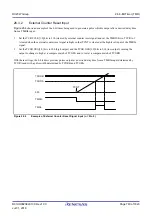
Conflict between TCNT Write and Counter Clear
If a counter clear signal is generated concurrently with CPU write to TCNT, the clear takes priority and the write is not
performed as shown in
Figure 26.13
Conflict between TCNT Write and Counter Clear
Counter clear signal
TCNT
PCLK
TCNT counter write by CPU
00h
N


