


9
raytecled.com
Raytec Global Tel: +44 (0) 1670 520055
Americas Tel: +1 613 270 9990
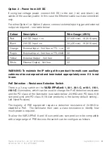
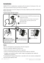
Option 2 – Power from 24V DC
If using low voltage power, connect 24V DC to the red (+ve) and black (-ve)
cables of the auxiliary cable. In this case the Ethernet cable is a data connection
only.
For either Option 1 or Option 2 above, connect external input trigger and external
output as required – see table below:
WARNING: To maintain the IP rating of the product the multi-core auxiliary
cable must be waterproofed and terminated appropriately even if it is not
in use.
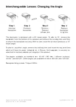
PoE Detection – Resistance Selection Switch
There is a 3 way switch on the
VAR2-IPPoE-w8-1, i8-1, i8-1-C, w16-1, i16-1,
i16-1-C
illuminators which can be used to change the PoE detection resistance
and the PD class of the illuminator (see table below -24.9KΩ and PD class 6 (8
size products) and PD class 8 (16 size products) is the factory default setting –
Left Hand Position).
The majority of PSE equipment require a detection resistance of 24.9KΩ to
establish a PoE. The illuminator then uses a class resistance to identify how
much power is required.
To allow the VAR2-IPPoE 8 and 16 size products size product to be compatible
with a large range of PSE devices the switch can be configure as follows
Colour
Description
Wire Gauge (AWG)
Red
24V DC Input +ve
22 (4/6 size); 18 (8/16 size)
Black
24V DC Input -ve
22 (4/6 size); 18 (8/16 size)
Orange
External Input - Volt free or TTL +ve
22
Purple
External Input - Volt free or TTL GND 22
Yellow
External Output - Volt free
22
White
External Output - Volt free
22


