


Chapter 5: Using the PDU
30
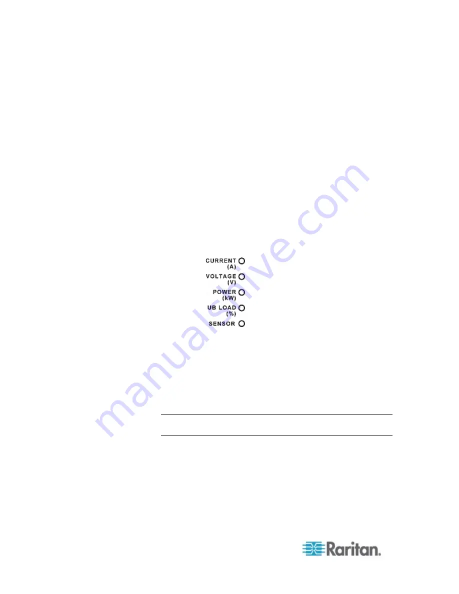
LEDs for Measurement Units
Five small LED indicators are on the LED display: four measurement
units LEDs and one Sensor LED.
The measurement units vary according to the readings that appear in the
three-digit row. They are:
Amp (A) for current
Volt (V) for voltage
Kilowatt (kW) for active power
Percentage (%) of the unbalanced load
One of the measurement unit LEDs will be lit to indicate the unit for the
value currently shown in the three-digit row.
The Sensor LED is lit only when PXE detects the physical connection of
any environmental sensor.
The five LEDs look similar to this diagram but may slightly vary according
to the model you purchased.
Two-Digit Row
The two-digit row shows the number of the currently selected line or inlet.
Values that may appear include:
L
x
: This indicates the selected line, where
x
is the line number. For
example, L2 represents Line 2.
Note: For a single-phase model, L1 current represents the Unit
Current.
AP: This indicates the selected inlet's active power.
Automatic Mode
When left alone, the LED display cycles through the line readings at
intervals of 10 seconds, as available for your PXE. This is the Automatic
Mode.
Summary of Contents for PXE
Page 16: ......
Page 339: ...Appendix A Specifications 323 RS 485 Pin signal definition al 4 5 6 D bi direction al Data 7 8...
Page 380: ...Index 364 Z Zero U Products 1...
Page 381: ......


