1269 User Manual
Configuring The 1269 2-12
8.
Install the other slide mounting assembly in the same
manner.
9.
Set the front dimension between the two slide mount
assemblies at 16-13/16 inches (+1/16,-0) and firmly
secure the front brackets to the mounting rail.
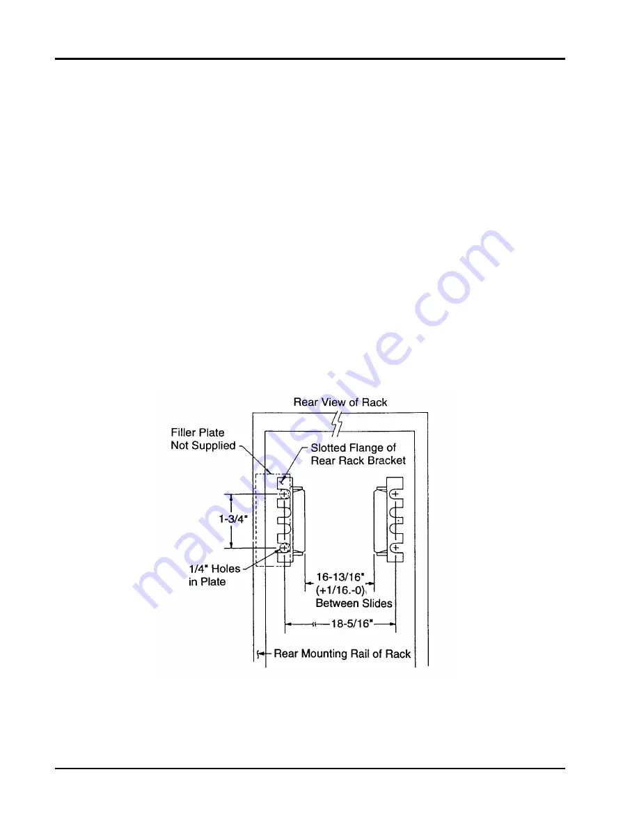
10.
The distance between the two slide mount assemblies at
the rear bracket should also be set at 16-13/16 inches
(+1/16,-0). Should a filler-plate be required to secure the
slide mount assembly to the rear rack mounting rail at 16
-13/16 inches (+1/16,-0), use the dimensions given in
Figure
2-7
to determine filler-plate size. The rear rack-
bracket may require adjustment to accommodate the
thickness of filler-plate.
11.
Firmly secure the rear rack bracket to the rear rack
mounting rail (or filler-plate) using two Phillips Panhead
#10-32 x ½ screws in each bracket (Item 13).
The slides are now positioned to accept the mainframe.
Figure 2-7 Rear End Slide Mount Rack Dimensions
Artisan Technology Group - Quality Instrumentation ... Guaranteed | (888) 88-SOURCE | www.artisantg.com