


1269 User Manual
Operating The 1269 3-9
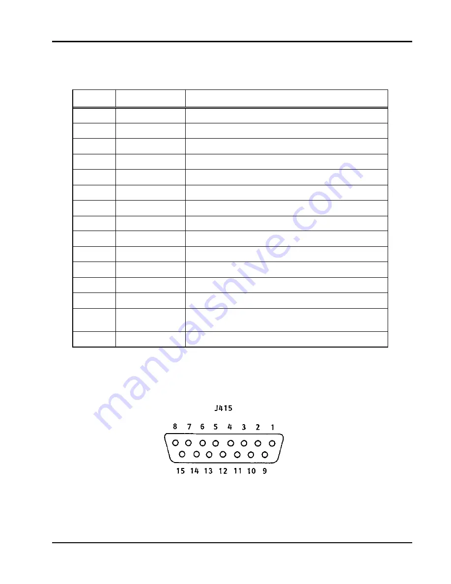
Table 3-6, J415 Rear Panel Monitor/Control Connector
Pin
Signal
Description
1
-24 VMON
VXIbus Voltage Monitor Output
2
+12 VMON
VXIbus Voltage Monitor Output
3
+5 VMON
VXIbus Voltage Monitor Output
4
-5.2 VMON
VXIbus Voltage Monitor Output
5
+5 STANDBY
5V Standby Input
6
ACFAIL*
VXIbus ACFAIL* Input or Monitor Output (see note)
7
GND
Logic Ground
8
RSV
Reserved
9
+24 VMON
VXIbus Voltage Monitor Output
10
-12 VMON
VXIbus Voltage Monitor Output
11
GND
Logic Ground
12
-2V MON
VXIbus Voltage Monitor Output
13
+24VHS
+24V House Keeping Supply Voltage Monitor Output
14
SYSRESET*
VXIbus SYSRESET* Input or Monitor Output (see
note)
15
R INHIBIT*
Power Supply Remote Inhibit Input
Note: Refer to VXIbus and VMEbus specifications for details on
using the ACFAIL* and SYSRESET* signals. If you use
these signals, do not violate VXIbus or VMEbus electrical
specification
.
Artisan Technology Group - Quality Instrumentation ... Guaranteed | (888) 88-SOURCE | www.artisantg.com


