Hardware Installation
3-6
3
3.
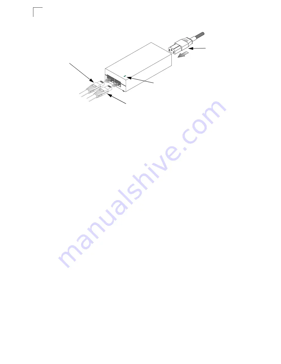
Insert the power cable plug directly into the standard AC receptacle on the
power injector.
4.
Plug the other end of the power cable into a grounded, 3-pin socket, AC power
source.
Note:
For International use, you may need to change the AC line cord. You must use a
line cord set that has been approved for the receptacle type in your country.
5.
Check the LED on top of the power injector to be sure that power is being
supplied to the wireless bridge through the Ethernet connection.
Align Antennas
After wireless bridge units have been mounted, connected, and their radios are
operating, the antennas must be accurately aligned to ensure optimum performance
on the links. This alignment process is particularly important for long-range
point-to-point links. In a point-to-multipoint configuration the Master bridge uses an
omnidirectional antenna, which does not require alignment, but Slave
bridges still need to be correctly aligned with the Master bridge antennna.
•
Point-to-Point Configurations
– In a point-to-point configuration the alignment
process requires two people at each end of the link. The use of cell phones or
two-way radio communication may help with coordination. To start, you can just
point the antennas at each other, using binoculars or a compass to set the general
direction. For accurate alignment, you must connect a DC voltmeter to the RSSI
connector on the wireless bridge and monitor the voltage as the antenna moves
horizontally and vertically.
•
Point-to-Multipoint Configurations
– In a point-to-multipoint configuration all
Slave bridges must be aligned with the Master bridge antenna. The alignment
process is the same as in point-to-point links, but only the Slave end of the link
requires precise alignment.
Input
Output
Ethernet cable
from LAN switch
Ethernet cable to
wireless bridge
AC power
Power LED indicator
Summary of Contents for WB2011
Page 1: ...User Guide...
Page 2: ......
Page 3: ...User Guide Guide Outdoor 5 GHz Wireless Bridge IEEE 802 11a Wireless Bridge...
Page 4: ...WB2011 F1 1 1 0 E102004 R01...
Page 14: ...Contents x...
Page 44: ...Initial Configuration 4 8 4...
Page 140: ...Command Line Interface 6 60 6...
Page 142: ...Troubleshooting A 2 A 5 If you forgot or lost the password Contact Technical Support...
Page 155: ...Index 4 Index...
Page 156: ......
Page 157: ...WB2011 E102004 R01...


