background image

Tables

xiv

Quantum TC2201E User’s Guide

Table 18

iSNS Server Configuration Menu...........................................114

Table 19

iSCSI Portal Group Configuration Menu..............................115

Table 20

Parallel SCSI Configuration Menu .........................................116

Table 21

SCSI Initiator Menu ..................................................................118

Table 22

SCSI Target Overrides Menu ..................................................119

Table 23

Parallel SCSI Buffered Tape Write Configuration Menu....120

Table 24

Device Mapping Main Menu ..................................................122

Table 25

Select Current Map...................................................................123

Table 26

Add a Map .................................................................................124

Table 27

Delete Current Map..................................................................125

Table 28

Map Edit Menu .........................................................................125

Table 29

Edit Map Name.........................................................................126

Table 30

Adding An iSCSI port Entry ...................................................127

Table 31

Device List for iSCSI Port ........................................................127

Table 32

Deleting an Entry......................................................................128

Table 33

Deleting Multiple LUNs ..........................................................129

Table 34

Fill Current Map .......................................................................130

Table 35

Clone Current Map...................................................................130

Table 36

 iSCSI Host List..........................................................................131

Table 37

iSCSI Host List...........................................................................132

Table 38

Adding a iSCSI Host ................................................................133

Table 39

Deleting a Host..........................................................................134

Table 40

Editing Host List for iSCSI Port..............................................135

Table 41

Utility Settings...........................................................................137

Table 42

Trace Settings ............................................................................138

Table 43

Trace Settings, Page 2...............................................................139

Table 44

Trace Settings, Page 3...............................................................140

Table 45

Trace Settings, Page 4...............................................................141

Table 46

Trace Settings, Page 5...............................................................142

Summary of Contents for TC2201E

Page 1: ...4XDQWXP 7 4XDQWXP 7 7 8VHU V XLGH 8VHU V XLGH 8VHU V XLGH 8VHU V XLGH 8VHU V XLGH...

Page 2: ...ication from time to time without notice COPYRIGHT STATEMENTS Copyright 2005 by Quantum Corporation All rights reserved Your right to copy this manual is limited by copyright law Making copies or adap...

Page 3: ...2201E Works 3 Processing SCSI Information 4 LAN free Backup and Restore 6 TC2201E Features 6 iSCSI Features 6 SCSI Bus Features 7 Management Features 7 TC2201E Benefits 7 Enterprise Class Performance...

Page 4: ...nterfaces and Connections 17 iSCSI Connections 18 SCSI Connection 19 Ethernet Management Connection 22 RS 232 Serial Management Connection 22 Setting Up Serial Port Communications 23 Connecting the Po...

Page 5: ...59 Main Menu Discovery 61 Main Menu iSCSI Mapping 62 Main Menu Statistics 67 Main Menu Utilities 68 Main Menu Utilities FTP Utility 69 Main Menu Utilities Trace Settings 72 Main Menu Utilities Current...

Page 6: ...ix B Inband SCSI 3 Commands 97 General Commands 98 Report LUNs Command 98 Inquiry Command 99 Vendor Unique Commands 102 Appendix C Using the Command Line Interface 103 Power Up Messages 104 Perform Co...

Page 7: ...FTP Interface 155 Backup Restore Configuration Settings 155 Configuration Backup Procedure 155 Configuration Restore Procedure 157 Get a Copy of Trace Buffer or Event Log 158 Update Firmware 159 Appe...

Page 8: ...Contents viii Quantum TC2201E User s Guide...

Page 9: ...and responses 5 Figure 7 LAN free backup 6 Figure 8 Installing Cage Nuts 14 Figure 9 Locating front of ear brackets 14 Figure 10 Attaching the Ear Brackets 15 Figure 11 Mounting at Front of Rack 16 Fi...

Page 10: ...r settings page 44 Figure 30 Real Time Clock Configuration Page 46 Figure 31 Factory Settings Reset Page 48 Figure 32 Ethernet Settings Page 49 Figure 33 Host name Page 50 Figure 34 Ethernet Port Conf...

Page 11: ...s Page 78 Figure 54 Display Event Log Page 80 Figure 55 Clear Event Log Page 81 Figure 56 SCSI Command Tracking 82 Figure 57 Features Page 84 Figure 58 Report page 85 Figure 59 Reboot Page 86 Figure 6...

Page 12: ...Figures xii Quantum TC2201E User s Guide...

Page 13: ...Inquiry Command 99 Table 7 Format of EVPD Page 0x80 100 Table 8 TC2201E LUN Inquiry Data 100 Table 9 Vendor Unique Commands 102 Table 10 Main menu 105 Table 11 Configuration menu 106 Table 12 User Se...

Page 14: ...t Map 125 Table 28 Map Edit Menu 125 Table 29 Edit Map Name 126 Table 30 Adding An iSCSI port Entry 127 Table 31 Device List for iSCSI Port 127 Table 32 Deleting an Entry 128 Table 33 Deleting Multipl...

Page 15: ...Statistics Menu 146 Table 51 Parallel SCSI Protocol Status Menu 146 Table 52 SCSI Device Display Menu 147 Table 53 SCSI Resource Display 148 Table 54 Event Log Menu 149 Table 55 SCSI Command Tracking...

Page 16: ...Tables xvi Quantum TC2201E User s Guide...

Page 17: ...tting Started introduces the TC2201E router and covers the installation of the router Chapter 3 Quantum Visual Manager discusses Ethernet visual management interface Chapter 4 Troubleshooting discusse...

Page 18: ...e following conventions Caution Cautions indicate potential hazards to equipment and are included to prevent damage to equipment Warning Warnings indicate potential hazards to personal safety and are...

Page 19: ...ational Standard for information systems dated March 9 1990 Copies may be obtained from Global Engineering Documents 15 Inverness Way East Englewood CO 80112 800 854 7179 or 303 397 2740 Contacts Quan...

Page 20: ...ca 949 725 2100 or 800 284 5101 Asia Pacific Rim International Code 61 7 3839 0988 Europe Middle East Africa International Code 44 0 1256 848748 Send faxes for the Customer Support Department to North...

Page 21: ...Ultra160 LVD SE SCSI buses Supported devices include Initiator Devices iSCSI hosts Direct Access Devices RAID controllers Disk drives JBODs Sequential Access Devices Tape drives Changer Devices Tape...

Page 22: ...SI interfaces are found on the back panel Also on the back panel Ethernet and Serial ports provide connections for configuration and management of the unit The LEDs operation indicators provide basic...

Page 23: ...it green the left indicator signifies iSCSI port activity SCSI Bus 0 1 When lit these green indicators signify SCSI activity on the bus corresponding to the number of the indicator Ethernet Link Act W...

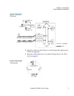
Page 24: ...lustrates steps 1 through 5 of the process 1 A iSCSI host issues a command The iSCSI host encapsulates the command in the iSCSI protocol and sends the packet to the TC2201E 2 The iSCSI controller in t...

Page 25: ...201E User s Guide 5 Figure 5 Information Processing 6 Data flows between the iSCSI host and SCSI target through payload buffers see figure 6 7 Response information flows from the SCSI target back to t...

Page 26: ...c from the LAN and onto a dedicated storage network The TC2201E supports LAN free backup restore environments see figure 7 Figure 7 LAN free backup TC2201E Features 1 iSCSI Features 1 The TC2201E prov...

Page 27: ...Ethernet TCP IP management access Port Serial 3 pin connector for terminal access DHCP for easier network administration Indexed and Auto Assigned addressing modes Support for SCSI 3 Commands Etherne...

Page 28: ...ual Manager VM software Store and forward allows configuration files and TC2201E operational settings to be saved and copied to other like routers reducing redundant setup tasks Using VM service profe...

Page 29: ...1 Physical Specifications 1 The physical specifications of the TC2201E are Internal power supply with detachable power cord iSCSI link status and activity LEDs SCSI Bus activity LEDs Ethernet link sta...

Page 30: ...on operating Environment 1 The non operating environment of the TC2201E is 40 to 65 C 10 to 90 Relative Humidity non condensing Power 1 The power requirements for the TC2201E are 100 240 VAC Auto Sens...

Page 31: ...types of devices Before physically installing the TC2201E consider carefully the location for the unit installation the intended use of the unit and the type of devices to which the unit will be atta...

Page 32: ...he shipping container Check each item for any damage Keep the TC2201E in the protective bag until you are ready to install it 2 Make sure you received all the equipment you ordered If an item appears...

Page 33: ...screws 8 M6x12 Phillips screws and 4 6 32x 312 Phillips screws Required Tools 2 The following tool is required for installation 2 PHILLIPS screwdriver Installing the TC2201E With Ear Brackets 2 To in...

Page 34: ...tting Started Mounting the TC2201E in a Rack 14 Quantum TC2201E User s Guide Figure 8 Installing Cage Nuts 5 Locate the front of the ear brackets as shown in figure 9 below Figure 9 Locating front of...

Page 35: ...tion Tighten the screws securely Figure 10 Attaching the Ear Brackets 7 If you are mounting the TC2201E in the rack with the ports facing inside the rack shown in Figure 2 4 or with the ports facing o...

Page 36: ...Chapter 2 Getting Started Mounting the TC2201E in a Rack 16 Quantum TC2201E User s Guide Figure 11 Mounting at Front of Rack...

Page 37: ...k of the Rack Once the TC2201E is installed you are ready to connect it to the other system components Interfaces and Connections 2 There are four types of interfaces to the TC2201E iSCSI SCSI RS 232...

Page 38: ...ll be connected Failure to correctly configure an iSCSI device may impair the operation of the network to which it is attached The iSCSI RJ 45 connectors on the unit can be directly connected to a sta...

Page 39: ...in the proper orientation SCSI Connection 2 The TC2201E can support Fast Ultra160 Narrow Wide SCSI depending on the specific configuration The TC2201E is factory configured to support LVD Single Ended...

Page 40: ...result in damage to the SCSI port connectors on the TC2201E Caution Do not plug HVD devices to an LVD SE bus Failure to heed this caution may result in severe damage to equipment Caution SCSI ports o...

Page 41: ...one of the SCSI connectors on the back panel of the unit The TC2201E should always be installed at the end of the SCSI bus 3 Make sure that the bus is terminated correctly By default the TC2201E is au...

Page 42: ...t capabilities include Telnet FTP and an HTTP web browser support for configuration and management Figure 18 TC2201E Ethernet port Ethernet Management port RS 232 Serial Management Connection 2 The 3...

Page 43: ...systems can use Hyperterminal Be sure the baud rate data bits stop bits parity and flow control are set correctly To set up serial communications with the TC2201E 1 Leave power to the TC2201E turned...

Page 44: ...ppropriate power cable as needed To connect the power cable to the TC2201E 1 Connect the female end of the power cable to the power connector on the back panel of the TC2201E 2 Plug the male end of th...

Page 45: ...r the Ethernet port as described in the next Chapter of this manual Figure 20 TC2201E Power Switch and Connector Reset Button Power switch Power connector Configuring the TC2201E 2 The TC2201E can be...

Page 46: ...4 In the Home page of the Visual Manager interface select Ethernet from the Main menu on the left 5 When the security prompt appears enter the appropriate user name and password values and then selec...

Page 47: ...ure may not apply to all situations but does address most key issues required for initial setup Configuring the TC2201D Using the Command Line Interface 2 To configure the TC2201E from the command lin...

Page 48: ...red on and check cable connections It may be necessary to perform a manual discovery select menu option 1 2 or 3 or to reboot the TC2201E from main menu Select X four times to return to the Configurat...

Page 49: ...C2201E sends a challenge message to the connection requestor The requestor responds with a value obtained by using a one way hash function 2 The TC2201E checks the response by comparing it its own cal...

Page 50: ...hance operation and security Buffered Tape Writes 2 Buffered Tape Writes is an option designed to enhance system performance By returning status on consecutive write commands prior to the tape device...

Page 51: ...d in HTML format in accordance with the W3C specification for HTML 3 2 Current W3C Recommendations and other technical documents can be found at http www w3 org TR Visual Manager allows access to conf...

Page 52: ...using the serial RS 232 connection a 3 pin serial cable is included with the TC2201E Current settings can be viewed and changed from the Ethernet Configuration Menu of the serial interface Note For m...

Page 53: ...tiated a session and has full access to the TC2201E QVM for the duration of the session A session ends when the user exits all instances of the web browser Log in will be required again via the TC2201...

Page 54: ...s chapter It is recommended that you navigate only using the Web page links contained in Visual Manager itself Depending on the Web browser used these links will often appear as highlighted text By cl...

Page 55: ...2201E Image A port side view figure 22 of the TC2201E is shown on the home page On all password protected pages of the Visual Manager interface the TC2201E image is interactive as described below Left...

Page 56: ...eft side of the TC2201E home page provides a list of menu items that are links to various TC2201E functions information and other menus Main Menu 3 The following are descriptions of the menu items lis...

Page 57: ...Chapter 3 Quantum Visual Manager Main Menu Quantum TC2201E User s Guide 37 Figure 24 System Page This page shows system status and allows configuration of standard system components and ports...

Page 58: ...baud rate for the serial port and allows it to be changed Figure 25 Serial port settings page To make any changes modify the entries by using the field s down arrow and selecting a choice Then select...

Page 59: ...configuration of iSCSI settings Figure 26 iSCSI Settings Page To make any changes modify the entries as described below and then select the Submit button iSCSI Target Settings Authentication can be t...

Page 60: ...ell as a field for Target CHAP Name Figure 27 iSCSI Authentication Settings Page CHAP Names are 1 to 255 characters in length and Initiator Target Secrets are 12 to 16 characters in length Target CHAP...

Page 61: ...lt the TC2201E is set to use one Portal Group for both ports which enables failover capability between the two iSCSI ports Use separate portal groups for each port This option disables failover capabi...

Page 62: ...ain Menu System iSNS Settings 3 This page allows for configuration of iSNS settings Figure 28 iSNS Settings Page iSNS servers maintain information about iSCSI clients and will respond to iSNS protocol...

Page 63: ...between Enabled and Disabled The default setting is Disabled When enabled the TC2201E will function as an iSNS client and will initiate transactions with iSNS servers using the iSNS Protocol The iSNS...

Page 64: ...ude the User Name and Password for the TC2201E The administrator user name and password should be unique and kept confidential It is recommended to use a combination of letters and numbers when creati...

Page 65: ...sword are forgotten it is possible to reset the user name and password to their default values by resetting the TC2201E to factory defaults from the Command Line Interface using the serial port see ap...

Page 66: ...ck Configuration 3 This page allows for set up of the date and time Figure 30 Real Time Clock Configuration Page To make any changes modify the entries as described below and then select the Submit bu...

Page 67: ...ed before the reset settings will take effect Note Be sure to correctly set the time and date in the Real Time Clock configuration menu so that event logging is accurate Note Resetting to factory defa...

Page 68: ...option is selected a confirmation message will appear to verify the selection If a response of Yes is given to the confirmation message current TC2201E activities will be disrupted while the unit res...

Page 69: ...r 3 Quantum Visual Manager Main Menu Quantum TC2201E User s Guide 49 Main Menu Ethernet 3 This page provides status and links for Ethernet and iSCSI port configuration pages Figure 32 Ethernet Setting...

Page 70: ...e is an alphanumeric entry of one word up to 255 characters long To change this entry select hostname from the Ethernet Menu to open the Hostname page From the hostname page changes to the hostname ca...

Page 71: ...rk settings IP address is the IP address of the TC2201E The default setting for the Ethernet port is 1 1 1 1 The default setting for iSCSI Port 0 is 169 254 1 1 The default setting for iSCSI Port 1 is...

Page 72: ...the setup of a lease reservation for an IP address if provided with the MAC address of the TC2201E This forces the DHCP server to always provide the same IP address to the TC2201E This setup is usefu...

Page 73: ...y recommended not to change this address Original Factory MAC address is the MAC address assigned by the hardware manufacturer to the Ethernet adapter in the hardware The TC2201E comes initialized wit...

Page 74: ...for viewing the current SCSI attributes and settings for buffered tape writes Figure 36 SCSI Bus Page To make any changes modify the entries as described below and then select the Submit button SCSI...

Page 75: ...default setting is Enabled Discovery Delay is the time in seconds that the TC2201E waits after a power up or reboot process which typically takes approximately 2 minutes before starting to discover S...

Page 76: ...vices that require special consideration during setup of the TC2201E Access to the Overrides Settings is reserved for authorized Quantum technicians Selecting the Go button opens a login prompt for wh...

Page 77: ...ing a SCSI Target ID 0 through 15 opens the SCSI target overrides page Figure 39 SCSI target Overrides Settings Page To finalize any changes for the override settings select the Submit button Wide Neg...

Page 78: ...Ultra SCSI 3 Negotiation enables disables Ultra SCSI 3 support for the selected Target ID This feature is useful for solving certain compatibility issues in mixed vendor environments where for exampl...

Page 79: ...ystem performance By returning status on consecutive write commands prior to the tape device receiving data Buffered Tape Writes remove the latency of waiting for responses from the tape device In the...

Page 80: ...orage device without using buffering but these writes may also be subsequently buffered when completion notices for earlier writes are received Maximum Bytes Outstanding determines the maximum number...

Page 81: ...ge From the Discovery Menu select the SCSI bus to view discover devices specific to that bus The Go button activates discovery for all the ports and buses or for just the selected port or bus When the...

Page 82: ...rom the list of ports shown in the menu under the heading Mapping Menu by left clicking on the desired port Figure 42 iSCSI Mapping Page After the iSCSI port has been selected mapping information for...

Page 83: ...ely after being submitted Caution Before activating any port mapping changes it is strongly recommended that the user verify there are not any command or data operations occurring in conjunction with...

Page 84: ...typed into the field boxes for Host Name iSCSI Name and Map Name The Map Name can be selected from the drop down list To make the changes permanent select the Submit button The following shows the sel...

Page 85: ...5 Figure 44 Select Current Map Page To completely clear the current map of all entries select the Clear Map button To fill the map select the fill option from the pull down list and then select the Fi...

Page 86: ...p item the Index Bus and Device can be selected from the pull down lists for either Discovered Device Entry or Manual Device Entry Discovered Device Entry is limited to devices already discovered Manu...

Page 87: ...67 Main Menu Statistics 3 This page shows SCSI bus statistics Figure 45 Statistics Page Select SCSI Statistics from the Statistics Menu on the left and then select the Go button to clear all current s...

Page 88: ...in Menu Utilities 3 This page allows access to the FTP utility and the settings and information for the event log and various trace options Select from the list of menu options shown under the heading...

Page 89: ...Chapter 3 Quantum Visual Manager Main Menu Quantum TC2201E User s Guide 69 Main Menu Utilities FTP Utility 3 This page provides access to an FTP Utility...

Page 90: ...P utility page The FTP Utility requires the use of a JAVA applet and will prompt for permission to install the applet if needed If you receive this prompt Note Internet access is required to verify th...

Page 91: ...o the TC2201E you can select from cfg configuration files and dlx firmware files formats For Downloads or files retrieved from the TC2201E you can select from cfg configuration files as well as from e...

Page 92: ...ration of trace settings Figure 48 Trace settings page Select the Submit button to submit changes for the Basic Trace Settings Page for trace logging of the TC2201E Select the Advanced Button to open...

Page 93: ...Guide 73 Figure 49 Advanced trace settings page For both the Basic and Advanced pages the default setting for each trace setting is Min track non error conditions but any or all settings can be chang...

Page 94: ...and Last Assert Traces menu options show the indicated trace information Current Traces shows data since the TC2201E was last booted Previous Traces shows data from the last boot cycle Last Assert Tra...

Page 95: ...Quantum Visual Manager Main Menu Quantum TC2201E User s Guide 75 Figure 50 Current TracesPage Trace buffers can be cleared by selecting either the Clear Current Traces option or the Clear Assert Trac...

Page 96: ...o be cleared Figure 51 Clear Current Trace Buffer Page When this option is selected a confirmation message will appear to verify the selection If a response of Yes is given to the confirmation message...

Page 97: ...be cleared Figure 52 Clear Assertion Trace Buffer Page When this option is selected a confirmation message will appear to verify the selection If a response of Yes is given to the confirmation message...

Page 98: ...This page allows set up of Event Log Settings Figure 53 Event Log Settings Page To make any changes modify the entries as described below and then select the Submit button Select from the Event Log s...

Page 99: ...Quantum TC2201E User s Guide 79 and then starts overwriting the log when full The default setting is All Events Logged Note So that event logging is accurate be sure to correctly set the clock and dat...

Page 100: ...Chapter 3 Quantum Visual Manager Main Menu 80 Quantum TC2201E User s Guide Main Menu Utilities Event Log 3 This page displays the Event Log Figure 54 Display Event Log Page...

Page 101: ...g to be cleared Figure 55 Clear Event Log Page When this option is selected a confirmation message will appear to verify the selection If a response of Yes is given to the confirmation message the uni...

Page 102: ...ceived or transmitted by the TC2201E Results are displayed in the Host Device ID Table While the TC2201E s current previous and last assert trace data does provide a complete summary of events in a ch...

Page 103: ...ng can also be cleared Toggling the clear option to the ON position and selecting the Submit button will clear all previous entries The settings for the Host Device ID Table are used to filter the tra...

Page 104: ...Figure 57 Features Page To enable an advanced software licensed feature enter a key number in the field and select the Add button To remove an advanced software licensed feature enter the key number a...

Page 105: ...Chapter 3 Quantum Visual Manager Main Menu Quantum TC2201E User s Guide 85 Main Menu Report 3 The report page presents a consolidated view of all system information Figure 58 Report page...

Page 106: ...When this option is selected a confirmation message will appear to verify the selection If a response of Yes is given to the confirmation message current TC2201E activities will be disrupted while th...

Page 107: ...ation of the unit Most problems are found in the initial installation In general it is wise to check all connections and review the configuration before proceeding with further trouble analysis Simpli...

Page 108: ...upport representative iSCSI Lnk Act When lit green the upper indicator signifies a good iSCSI link on the port When lit green the lower indicator signifies iSCSI port activity If the Link indicator fa...

Page 109: ...is configured serial configuration settings can also be set via telnet Verify SCSI Bus Configuration 4 Problems with SCSI bus configuration are common Basic operation of a SCSI bus can be checked by u...

Page 110: ...When the TC2201E is connected and powered on this link indicator should show a good link If it does not check the cabling or connections As a means of verifying link integrity when connected to a func...

Page 111: ...iguration 4 In some cases it may be that the iSCSI host bus adapter or host device driver may not be working properly Check the configuration of these elements It may be useful to check the release no...

Page 112: ...Chapter 4 Troubleshooting Basic Verification 92 Quantum TC2201E User s Guide...

Page 113: ...the 3 pin serial connection are in reference to the serial receptacle on the rear panel of the TC2201E Use an RS 232 null modem cable to connect the TC2201E to the host system Table 1 RJ 11 Pin Assign...

Page 114: ...to a terminal or a computer running terminal emulation software The pin assignments given in Figure A 2 for the DB 9 serial connection are in reference to the serial connector at the end of the cable...

Page 115: ...5 Ethernet connection are in reference to the Ethernet receptacle on the back panel of the TC2201E The TC2201E Ethernet connection supports the IEEE specifications for 10BASE T and 100BASE TX Ethernet...

Page 116: ...nments RJ 45 Ethernet Pin Assignments 96 Quantum TC2201E User s Guide Pin 3 Receive In Pin 4 No Connection Pin 5 No Connection Pin 6 Receive In Pin 7 No Connection Pin 8 No Connection 1 2 3 4 5 6 7 8...

Page 117: ...he TC2201E itself When using SCSI 3 commands to access general management features the commands can be sent to device LUNs that are mapped through the TC2201E The following is a list of the SCSI 3 com...

Page 118: ...Command 2 The TC2201E supports the Report LUNs command The Report LUNs command will return a list of Logical Unit Numbers LUNs that can receive commands The format of the report LUNs command is shown...

Page 119: ...5 Reserved 6 Reserved 7 Reserved LUN list 0 7 First LUN 0 7 Last LUN All LUNs are reported and will appear in the host s map Inquiry Command2 The format of the Inquiry Command is shown in Table B 3 T...

Page 120: ...D Page 0x80 Bit Byte 7 6 5 4 3 2 1 0 0 Device Type 0ch 1 Page Code 80h 3 Reserved 4 Page Length 5 20 Serial Number The serial number field is a sixteen byte left justified ASCII string Device Identifi...

Page 121: ...0x00 ISO Version 0x00 AENC 0x00 TrmIOP 0x00 Response Data Format 0x02 SCSI 2 Inquiry Data Format Additional Length 0x20 RelAdr 0x00 Wbus32 0x00 Wbus16 0x00 Sync 0x00 Linked 0x00 CmdQue 0x00 SftRe 0x00...

Page 122: ...on about these vendor unique commands please contact your service representative Table 9 Vendor Unique Commands Command Description Device Type E7 Initialize Element Status Tape Medium Changer B8 Read...

Page 123: ...rface CLI The TC2201E allows the user to access many configuration settings through the CLI Among these settings are Baud rate of the serial port Ethernet IP and MAC addresses Device Mapping Trace lev...

Page 124: ...power up self tests are performed while the TC2201E starts which can take up to 2 minutes and messages related to these tests will be visible from the serial port If completed successfully the main me...

Page 125: ...tilities menu If you enter Y for Yes the TC2201E will restart This option is further described later in this chapter Select 5 to access the Advanced Software Licensed Features menu This option is desc...

Page 126: ...are not case sensitive You can enter uppercase and lowercase characters interchangeably whenever menus indicate letters as choices Configuration Menu X XX XXXX XXXXXX XXXXXXXXXXXXXX 07 26 2005 08 56 2...

Page 127: ...rate is 115200 User Settings X XX XXXX XXXXXX XXXXXXXXXXXXXX 07 26 2005 08 56 22 Current Username root 1 Change Username 2 Change Password X Return to previous menu Note In the event that either or b...

Page 128: ...k settings for the management port including DHCP configuration IP address subnet mask gateway Ethernet MAC address DNS settings and Ethernet MTU size Baud Rate Configuration Menu X XX XXXX XXXXXX XXX...

Page 129: ...nce DHCP is enabled it is necessary to save the current configuration and reboot the TC2201E before an IP address will be requested from the DHCP server Use the following four steps Ethernet Configura...

Page 130: ...isual Manager Because the method of setting up a lease reservation varies depending on the DHCP server being used it is recommended you contact your Network Administrator for assistance For more infor...

Page 131: ...y com shown above is an example of how a DNS Domain name could appear Select 7 to change the Maximum Transmission Unit MTU for Ethernet This setting can be configured for 1500 or 9000 byte frames The...

Page 132: ...When this menu item is selected the names and secrets for CHAP authentication can be configured These settings must match the same settings on hosts that need to log into the target devices Host setti...

Page 133: ...racters and secrets are 12 to 16 characters Select 3 to delete a device from the CHAP authentication list Select 4 to change the settings for a device currently using CHAP authentication Select 5 to d...

Page 134: ...ettings iSNS servers maintain information about iSCSI clients and will respond to iSNS protocol queries and requests and initiate iSNS protocol State Change Notifications Selecting this menu option op...

Page 135: ...ch effectively enables failover capability between the two iSCSI ports Table 19 iSCSI Portal Group Configuration Menu Following are descriptions for each of the settings Select 1 to use one Portal Gro...

Page 136: ...nu to the next SCSI bus Select 1 to edit the SCSI Initiator menu settings described later in the chapter Select 2 to enable disable SCSI Discovery Parallel SCSI Configuration Menu X XX XXXX XXXXXX XXX...

Page 137: ...n Time Quantum recommends you set the value to at least 2 seconds to ensure all SCSI devices complete their individual power ups With Discovery enabled the Discovery Delay will lengthen the time taken...

Page 138: ...SI Initiator ID Select 3 to select an alternate SCSI Initiator ID This should be a unique ID on the bus The default value is 6 This option is used to enhance the performance of status agent commands i...

Page 139: ...e Negotiation enables disables the option for negotiation on a wide SCSI bus Note Normally override settings should not be changed except when directed to do so by an authorized Quantum technician SCS...

Page 140: ...hat cannot handle automatic negotiation of the bus speed or possibly where there is a device that does negotiate to use Ultra SCSI 3 but somehow cannot actually handle the speed Parallel SCSI Buffered...

Page 141: ...ve been successfully completed and data has been successfully written to the medium This is appropriate for such tasks as file backup restore Select 2 to set Maximum Writes Outstanding This setting de...

Page 142: ...his map Table 24 Device Mapping Main Menu Changing Ports When the iSCSI Portal Groups setting is configured to use Both Ports pressing the Enter key will have no effect on this menu When the iSCSI Por...

Page 143: ...d initiators Table 25 Select Current Map Enter the number from the column on the left side of the table to select a map and make it Current For example entering 2 from the picture above would select m...

Page 144: ...an address on iSCSI Port 0 Select 3 from the Device Mapping Main Menu to add a map This option allows adding a new map for the current protocol port or bus Once the map is created it becomes the curre...

Page 145: ...map Editing an Auto Assigned is not allowed Table 28 Map Edit Menu This will delete current map New Map ID 3 Are you sure y n y Map New Map with ID 3 was deleted Map Edit Menu X XX XXXX XXXXXX XXXXXXX...

Page 146: ...Entry 3 To add a new entry the user must enter the desired Index If the selected Index is already present in the map the user will be asked to confirm the override or enter different address informat...

Page 147: ...crolling up and down the device list X will bring the user back to the Edit Map Entries display table Creating an Entry 3 The user can create an empty map or use an existing map to pre enter devices t...

Page 148: ...move Gaps 3 This option removes any incremental gaps in the sequence of LUNs listed in the table Deleting an Entry 3 The user selects a LUN ID Table 32 Deleting an Entry Select D to delete multiple LU...

Page 149: ...ices at the end of the current map Devices marked as DOWN will not be mapped After this operation completes the Edit Map Entries screen will appear Select Idx to delete X Cancel D DeleteMultiple d Ent...

Page 150: ...y existing map Table 35 Clone Current Map Select 7 from the Device Mapping Main Menu to edit the host list for the current port protocol The Current map can be associated with hosts available in the h...

Page 151: ...he user can edit delete or change name for the host Entering a host number index opens the iSCSI Host Info Display where the selected host can be associated with the current map Host List Edit Display...

Page 152: ...Host 3 Select A to add a host to the list The user will be prompted to enter the desired Host Name and iSCSI Initiator Name Duplicate hosts won t be added to the list iSCSI Host Info Display X XX XXXX...

Page 153: ...domain name used in this format and SHOULD be the first month in which the domain name was owned by this naming authority at 00 01 GMT of the first day of the month This date code uses the Gregorian c...

Page 154: ...alified name string is as follows iqn 1986 03 com hp hpfcs214 2000853943 With the successful addition of the host the host list will then be displayed again and the user can confirm that the host info...

Page 155: ...XXXXXXXXXXXXX 07 26 2005 08 56 22 Current Map iSCSI Portal Group Both Ports Indexed iSCSI Portal Group Both Ports Host List Idx Initiator iSCSI Name 1 iqn 1991 05 com microsoft iscsitc3win Page 1 out...

Page 156: ...nsfers with that device It is the user s responsibility to ensure that no operations will be negatively impacted due to the activation of mapping changes Trace and Event Settings Configuration 3 This...

Page 157: ...tings configuration Trace Configuration 3 This option allows trace levels to be set These settings should not be modified in normal operation as performance degradation may result There are two pages...

Page 158: ...of notifications that will be received The lower the trace level setting fewer notifications will be received Trace Settings X XX XXXX XXXXXX XXXXXXXXXXXXXX 07 26 2005 08 56 22 0 Flash File Parser FFP...

Page 159: ...o set the clock and date in the Real Time Clock Configuration menu so trace logging is accurate Trace Settings X XX XXXX XXXXXX XXXXXXXXXXXXXX 07 26 2005 08 56 22 0 Management Async ASY 0 Minimum 1 Ma...

Page 160: ...Kernel RLK 0 Minimum 1 Routing Layer User RLU 0 Minimum 2 Routing Layer Mapping Kern RMK 0 Minimum 3 Routing Layer Mapping User RMU 0 Minimum 4 SCSI Driver PSD 0 Minimum 5 SCSI Transport PST 0 Minimum...

Page 161: ...22 0 iSCSI Driver ISD 0 Minimum 1 iSCSI Transport IST 0 Minimum 2 iSCSI Management ISM 0 Minimum 3 iSCSI PL ISP 0 Minimum 4 iSCSI RMI ISR 0 Minimum 5 iSCSI HAL ISH 0 Minimum 6 iSCSI SCBI translator I...

Page 162: ...displayed trace settings to become effective immediately without requiring a reboot or power cycle Trace Settings X XX XXXX XXXXXX XXXXXXXXXXXXXX 07 26 2005 08 56 22 0 LSCSI Driver LSD 0 Minimum 1 LS...

Page 163: ...t configuration changes to the TC2201E now Event logging captures over 2000 events and then starts overwriting the log when full Event Log Filter Settings X XX XXXX XXXXXX XXXXXXXXXXXXXX 07 26 2005 08...

Page 164: ...red as single digits for instance 6 instead of 06 Save Configuration 3 This option saves the current configuration state in FLASH which updates the saved previous configuration state Saved changes are...

Page 165: ...user name and password are not retained after the TC2201E resets The handles resets differently as described in the note below System Utilities 3 Table 49 Sysem Utility Menu Note Resetting to factory...

Page 166: ...n this chapter System Statistics 3 Table 50 Sysem Status Statistics Menu Select 1 from the System Status Statistics Menu to display Parallel SCSI Protocol Status Table 51 Parallel SCSI Protocol Status...

Page 167: ...3 to issue boot discovery includes resets and delays Select 4 to display all local SCSI devices Select 5 to display local devices on the specified SCSI bus Select 3 from the Parallel SCSI Protocol St...

Page 168: ...is displayed SCSI Resource Display X XX XXXX XXXXXX XXXXXXXXXXXXXX 07 26 2005 08 56 22 psActiveInitiatorFreeQ 1023 psCmdFreeQ 0 psLocalDeviceFreeQ 249 psLocalHostFreeQ 16 psManFreeQ 15 psNotifyFreeQ 1...

Page 169: ...use after each Report Section Press n for no pause any other key to pause The report includes detailed information about the hardware platform bootup initialization serial port settings iSCSI settings...

Page 170: ...thru 4 are also available from this menu Select 2 to display the SCSI Command Tracking information for all selected hosts and devices Select 3 to set the data to be displayed in terms of Type Device H...

Page 171: ...e last assertion failure Select 4 to clear the current trace buffer If cleared then the Display trace from current boot cycle option will not show any data Select 5 to clear the assert trace buffer If...

Page 172: ...When this option is selected from the main menu the Advanced Software Licenses Features menu is displayed Table 57 Advanced Software Licences Menu Select 1 to add a license key Select 2 to disable a l...

Page 173: ...al or terminal emulator connected to the serial port of the TC2201E 1 From the Main menu select the Download a New Revision of The Firmware option to start the download procedure 2 When you confirm yo...

Page 174: ...mage and copies that image to the boot sector of the FLASH and then boots with that image At that point the TC2201E is using the new firmware The following figure shows what you might see on your term...

Page 175: ...on settings over FTP This allows users to maintain multiple setting configurations externally from the TC2201E and to be able to restore any of the configurations as needed When backing up configurati...

Page 176: ...x lcd c myCfg Note If the TC2201E is to use a static IP address the default IP address 1 1 1 1 should be changed to an address that is appropriate for the IP network it will reside on Note that the de...

Page 177: ...d the TC2201E will reboot The TC2201E will then be using the configuration Note If the TC2201E is to use a static IP address the default IP address 1 1 1 1 should be changed to an address that is appr...

Page 178: ...command For the current trace buffer use get curtrace txt For the previous trace buffer use get prvtrace txt For the assert trace buffer use get assertlog txt For the current event log use get eventlo...

Page 179: ...name and password for the password 4 Specify binary mode bin 5 Specify the firmware s path and filename dlx file with the put command put path filename dlx The file will transfer and the TC2201E will...

Page 180: ...Update Firmware 160 Quantum TC2201E User s Guide...

Page 181: ...MC Legato NetWorker Procedure B Veritas NetBackup Procedure C Veritas Backup Exec Procedure D CA Brightstor ARCserve Procedure E Bakbone NetVault Procedure F HP Data Protector Procedure G CommVault Ga...

Page 182: ...a key named Device open the Parameters key by selecting Edit Add Key and enter Device for Key Name 5 To create a DWORD named MaximumSGList open the Device key by selecting Edit DWORD and entering Max...

Page 183: ...s Guide 163 Figure 62 Registry Editor Procedure B Veritas NetBackup 5 1 Create a file called C Program Files Veritas NetBackup db config SIZE_DATA_BUFFERS Note The largest bock size support by NetBack...

Page 184: ...28 in decimal bytes 3 Run the backup process Procedure C Veritas Backup Exec 5 1 Within Backup Exec application as shown in figure 63 click on the Devices tab 2 Right click on one of the tape drives d...

Page 185: ...erve 5 1 Determine the correct block size For BrightStor ARCserve Backup 11 0 11 1 for Windows the block size of tape drive can be found in HKEY_LOCAL_MACHINE SOFTWARE ComputerAssociate BrightStor ARC...

Page 186: ...analyze the performance to determine set the appropriate block size Procedure E Bakbone NetVault 5 1 When the library is configured click on NetVault Device Management as shown in figure 64 2 Click o...

Page 187: ...odifying the Registry restart the computer Drivers read MaximumSGList at boot time The actual formula that a Windows class driver uses to determine the maximum transfer size is maximum size number of...

Page 188: ...have for example three aic78xx based SCSI channels on your system change the appropriate Device0 Device1 or Device2 value If you want to set all adapters at the same time specify MaximumSGList for Dev...

Page 189: ...G CommVault Galaxy 5 To increase block size do the following 1 Using the CommVault Resource Pack CD navigate to the folder titled setFlushBlockSize 2 Copy SetFlushBlockSize executable to the Galaxy C...

Page 190: ...Gb 16 Gb or 32 Gb For Galaxy 5 0 Users 1 Using the CommVault Resource CD navigate to the folder titled SetChunkSize 2 Copy SetChunkSize executable to the Galaxy Commserver install directory Base dire...

Page 191: ...4 GB 8 GB 16 GB 32 GB by default it shows the current value for the selected appType For Galaxy 5 9 Users 1 Open the CommCell Console For Java GUI 2 Open Control Panel and then click on Job management...

Page 192: ...Procedure G CommVault Galaxy 172 Quantum TC2201E User s Guide...

Page 193: ...Used to create a mapping table that maps devices on the SCSI bus to Fibre Channel logical units area The second byte of the N_Port Identifier authentication A process of identification usually based...

Page 194: ...bus definition see SCSI Bus C channel A general term for a path on which electronic signals travel CHAP Challenge Handshake Authentication Protocol a security access control protocol networks cluster...

Page 195: ...fabric An iSCSI term that includes iSCSI Arbitrated Loop Switched Fabric and Point to Point fault LED During power up and self test the TC2201E Fault LED comes on After self test if this LED remains...

Page 196: ...nternet protocol iSCSI Internet SCSI iSCSI is Internet SCSI Small Computer System Interface an Internet Protocol IP based storage networking standard for linking data storage resources developed by th...

Page 197: ...n F Port interconnected by a pair of optical or copper links one inbound and one outbound LUN Logical Unit Number or Logical Unit a subdivision of a SCSI target For SCSI 2 each SCSI target supports up...

Page 198: ...ilable for access Taking a iSCSI adapter offline means ending inputs outputs and suspending all transactions going from the TC2201E to the specified iSCSI device online For the TC2201E online indicate...

Page 199: ...uting decision is based on paths between address mappings among dispersed initiators and targets router to router Configuration involving at least two routers where one router is in Initiator Mode and...

Page 200: ...CSI data between SCSI devices It is an 8 bit or 16 bit bus that supports up to eight or sixteen devices including itself in any mix of initiators and targets with the limitation that at least one init...

Page 201: ...the ends of the cable The SCSI bus requires termination at both ends of the bus One end of the SCSI bus is terminated by the SCSI adapter s internal termination The other end should have a terminator...

Page 202: ...Glossary 182 Quantum TC2201E User s Guide...

Reviews: