background image

Chapter 3: F2000 Basic Operations
View and Download Logs

54

Quantum F2000 User’s Guide

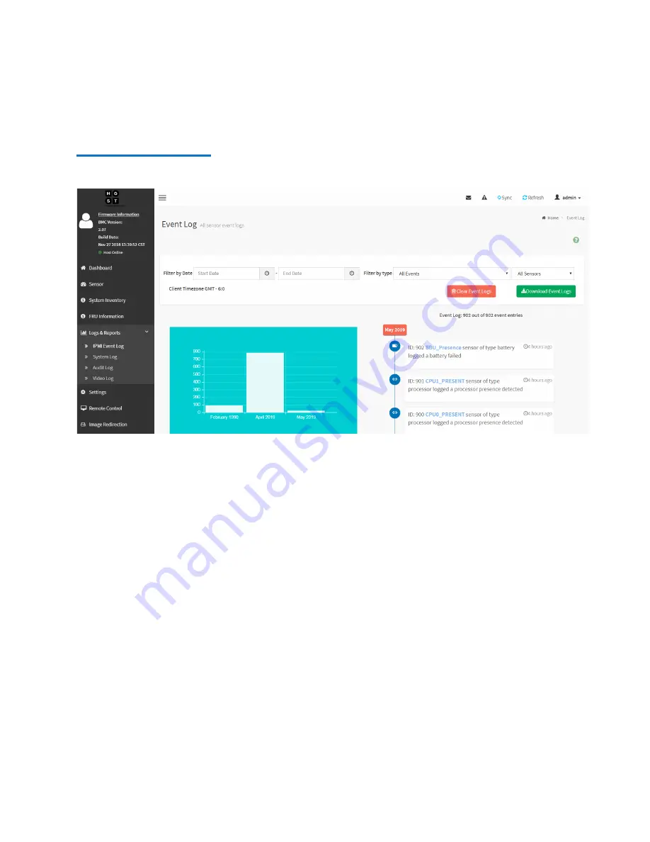
Figure 39  IPMI Event Log Page

4

Use the following filters to filter the log data as needed:

Filter by Date

: allows you to select a start and end date for the 

log data.

Filter by type

: allows you to select 

All events

 or a specific type 

of event to report in the log data. 

5

Click 

Download Event Logs

 to download the log file. 

The IPMI Event Log will be named 

SELLog.txt

.

Summary of Contents for F2000

Page 1: ...User s Guide Quantum F2000 6 68750 01 Rev A...

Page 2: ...ion of the law TRADEMARK STATEMENT Artico Be Certain and the Q brackets design DLT DXi DXi Accent DXi V1000 DXi V2000 DXi V4000 DXiV Series FlexTier Lattus the Q logo the Q Quantum logo Q Cloud Quantu...

Page 3: ...torage Environment 3 Quantum Cloud Storage Platform 4 F2000 and NVMe Benefits 5 So What is NVMe 5 Lighting Fast Performance 5 Designed for the Future 5 SAS Architecture vs NVMe Architecture 6 F2000 Ha...

Page 4: ...he BMC Web UI 28 Supported Browsers 28 BMC Web UI Overview 29 Access the BMC Web UI 30 Create Users or Update User Settings 35 Power Off a Canister System 39 Power Off Considerations 39 Power Off Proc...

Page 5: ...Replacement 117 Required Tools 117 Interface Card Replacement Considerations 117 Remove an Interface Card 117 Install an Interface Card 127 PIB Canister Replacement 134 Required Tools 134 PIB Caniste...

Page 6: ...Contents vi Quantum F2000 User s Guide Identify a Degraded SSD 173 Remove an SSD Assembly 175 Install an SSD Assembly 178 Glossary 183...

Page 7: ...nt overviews Basic operations Customer replaceable unit CRU instructions Audience This manual is written for F2000 System users System administrators Field Service Engineers Prerequisites Prerequisite...

Page 8: ...Chapter 4 F2000 Customer Replaceable Units CRUs provides removal and installation procedures for CRUs Glossary Notational Conventions This manual uses the following conventions Convention Example Use...

Page 9: ...ft side of the system Refers to the left side as you face the component being described Product Safety Statements Quantum will not be held liable for damage arising from unauthorized use of the produc...

Page 10: ...Preface x Quantum F2000 User s Guide...

Page 11: ...Quantum office locations go to http www quantum com aboutus contactus index aspx Document No Document Title Document Description 6 68748 01 F2000 Release Notes Provides compatibility information known...

Page 12: ...eck backup software and operating system support and locate manuals FAQs firmware downloads product updates and more in one convenient location Benefit today at http www quantum com serviceandsupport...

Page 13: ...s Team for faster more precise root cause diagnosis StorageCare Guardian is simple to set up through the Internet and provides secure two way communications with Quantum s Secure Service Center Learn...

Page 14: ...um F2000 User s Guide Worldwide End User Product Warranty For more information on the Quantum Worldwide End User Standard Limited Product Warranty http www quantum com serviceandsupport warrantyinform...

Page 15: ...an overview of the Quantum F2000 array and its components and includes the following sections Product Overview on page 2 F2000 in a StorNext Shared Storage Environment on page 3 Quantum Cloud Storage...

Page 16: ...cess RDMA networking technology to provide direct access between workstations and the NVMe storage devices to provide predictable ultra fast network performance Lastly both the software and hardware a...

Page 17: ...k without the bottlenecks associated with current storage and networking technologies The result is dramatically lower and predictable latencies for anyone working in Ultra High Definition UHD and hig...

Page 18: ...d Storage Platform is Software defined Run on bare metal in a virtual machine or in the cloud No hardware dependence Highly available With capabilities that include active active clustering failover a...

Page 19: ...out data contention support playout to multiple digital intermediaries from a single volume or work effortlessly with uncompressed 8K content the F2000 supports all these workflows and more It does th...

Page 20: ...PU cores have to go through a single SAS HBA for storage access which creates a central bottleneck for all I O With NVMe architecture there is no central bottleneck for I O Every CPU core can talk to...

Page 21: ...nnectivity specifically designed for the highest performance and availability See Figure 5 for an overview of the main F2000 hardware components Figure 5 Main F2000 Components Item Component 1 Drive B...

Page 22: ...under typical conditions Redundant Canisters The F2000 contains redundant hot swappable canisters Each canister contains Dual Xeon 6140 CPUs 2 3 GHz 18 C 140 W 4 x 32 GB ECC RDIMM DDR4 2666 MHz 128 G...

Page 23: ...and includes the following sections Front Components on page 10 Rear Components on page 11 System LEDs on page 13 Canister Description on page 17 Chassis Description on page 18 Fan Module Description...

Page 24: ...n Volatile Memory Express NVMe Solid State Drives SSDs The SSDs are numbered from 1 to 24 going left to right The drive slot number is printed at the bottom of the chassis below the SSD drive assembli...

Page 25: ...ts and the same number of PCIe slots However the top canister is inverted when compared to the bottom This means that the port labeling and PCIe slot numbering is in the reverse order from left to rig...

Page 26: ...hannel cards are shown installed in PCIe slots 1 and 2 in Figure 7 For more details about interface cards refer to Interface Card Descriptions on page 20 6 Port 1 10 GbE RJ45 7 Port 2 10 GbE RJ45 8 VG...

Page 27: ...lable on the left side of the system and are visible with or without the Quantum bezel installed See Figure 8 for an example of the LEDs with the bezel installed Figure 8 Front Chassis LEDs Quantum Be...

Page 28: ...op canister is inverted so the LEDs on that canister are located at the top right of the canister See Figure 9 for the locations and descriptions of the LEDs Figure 9 Rear Canister LEDs Item LED Actio...

Page 29: ...U LED The PSU Fault led is located in the same position on PSU A and PSU B See Figure 10 for the location and description of the LED Figure 10 PSU LED Location Item LED Action 1 Power Off PSU power of...

Page 30: ...t the top of the SSD drive carrier See Figure 11 for the locations and descriptions of each LED Figure 11 SSD LED Locations Item LED Action 1 Drive Fault LED Amber solid or blinking Degraded drive rep...

Page 31: ...CPUs DIMMs and M 2 Boot Drives are all contained inside the canisters The redundancy of the canisters is designed so that the system can run on one canister in the event that the other canister fails...

Page 32: ...cated at the front which houses all 24 of the data SSDs The rear of the chassis contains PSU bays and two canister bays see Figure 13 on page 18 The major system components such as the fan modules CPU...

Page 33: ...ng for the F2000 The fan module is installed inside the canister in close proximity to the canister components to provide efficient cooling to system components An F2000 system contains 10 fan modules...

Page 34: ...e following Fibre Channel FC or Ethernet interface card configurations 4 x 32 Gb FC Dual Port QLogic 2742 cards per system see Figure 15 2 x 100 GbE Dual Port Mellanox ConnectX 5 cards per system see...

Page 35: ...Chapter 2 F2000 Component Overviews Interface Card Descriptions Quantum F2000 User s Guide 21 Figure 16 100 GbE Dual Port Mellanox ConnectX 5...

Page 36: ...nister houses the PIB that extends the connection of the PSU to the midplane The PIB canister contains a PSU connector that attaches to the PIB The other end of the PIB canister contains a card edge c...

Page 37: ...tinum certified and utilize C14 power cable receptacles See Table 1 for more PSU specifications Table 1 PSU Specifications Note The system power supply units PSUs require high line voltage 200 240 VAC...

Page 38: ...Chapter 2 F2000 Component Overviews PSU Description 24 Quantum F2000 User s Guide Figure 18 PSU Components Item Description 1 Latch Release Lever 2 Power Receptacle 3 Fan 4 Handle 5 Connector...

Page 39: ...the rear of the chassis for servicing see Figure 19 The rack rails contain a rack ear locking mechanism on both sides to secure the chassis in the rack during basic servicing procedures The rack ear...

Page 40: ...SD assembly is comprised of two parts SSD and drive carrier See Figure 20 to identify the main components of the SSD assembly Figure 20 SSD Assembly Components Note See SSD LEDs on page 16 for details...

Page 41: ...on page 28 BMC Web UI Overview on page 29 Access the BMC Web UI on page 30 Create Users or Update User Settings on page 35 Power Off a Canister System on page 39 Power On a Canister on page 43 Identif...

Page 42: ...r access reports logs and create update new users Supported Browsers Table 2 provides information about the web browser and operating system OS support for the BMC Web UI Table 2 Web Browser and OS Su...

Page 43: ...Figure 21 BMC Web UI Overview Quick Button Menu The Quick Buttons Menu provides active user information and functions The Messages and Warning buttons display information without having to leave the...

Page 44: ...ns that contain diagnostic information related to the current running conditions You can click each section on the Dashboard to quickly access additional information Access the BMC Web UI To access th...

Page 45: ...ess the Network and Sharing Center control panel To do this press the Windows key on the keyboard type view network status and devices and press Enter 2 On your notebook computer access the Network an...

Page 46: ...on your macOS version 1 Select the Apple menu System Preferences Network and select the Ethernet connection In the Configure IPv4 drop down list select Manually 2 Enter the IP address and subnet mask...

Page 47: ...e 23 Figure 23 BMC Web UI Login Screen 2 Log in to the BMC Web UI The default credentials are Username admin Password admin Note For instructions on how to change the default admin password and or cre...

Page 48: ...Chapter 3 F2000 Basic Operations Use the BMC Web UI 34 Quantum F2000 User s Guide Figure 24 BMC Web UI Dashboard...

Page 49: ...to update the default admin user credentials and create additional users To update the admin user account settings or create a new user 1 From the BMC Web UI Dashboard click Settings from the left me...

Page 50: ...s Guide Figure 26 User Management Configuration Page 3 Do one of the following Click an existing user account card such as admin to update an existing account Click an unassigned user card to create...

Page 51: ...Chapter 3 F2000 Basic Operations Create Users or Update User Settings Quantum F2000 User s Guide 37 Figure 27 User Management Configuration Page Example...

Page 52: ...lows the user access to all functions within the BMC Web UI The other user privilege levels contain limitations to what functions and features can be accessed or configured KVM Access Enables remote K...

Page 53: ...e F2000 for maintenance purposes you must power off both canisters and unplug the power cables from the PSUs Power Off Considerations If you power off the entire F2000 system both canisters be sure to...

Page 54: ...Figure 28 Power Control Page 3 Verify that you are powering down the correct canister You can do this by identifying the specific canister listed on the screen in the Current Canister Position inform...

Page 55: ...e any of the options under Peer canister Host is currently on section 5 Click Perform Action The system displays a dialog window with the message Are you sure to perform this operation 6 Click OK The...

Page 56: ...ister System 42 Quantum F2000 User s Guide Figure 30 Fault LED on the Front of System and Rear of the Bottom Canister Item LED Action 1 System Fault Amber solid Fault conditions exist 2 Canister Fault...

Page 57: ...PMI BMC port on the other canister b Repeat Step 1 on page 39 through Step 6 to power off the second canister c Disconnect the power cables from the PSUs to completely remove power from the system Pow...

Page 58: ...gure 31 Power Control Page 3 Verify that you are powering on the correct canister You can do this by identifying the specific canister listed on the screen in the Current Canister Position information...

Page 59: ...canister Host is currently on section 5 Click Perform Action The system displays a dialog window with the message Are you sure to perform this operation 6 Click OK The system then displays the follow...

Page 60: ...ions Power On a Canister 46 Quantum F2000 User s Guide Figure 33 Power LED on the Front of System and Rear of the Bottom Canister Item LED Action 1 System Power Green solid Power on 2 Canister Power G...

Page 61: ...Identify LED on the front of the chassis using the BMC Web UI To turn on the blue Identify LED 1 Access the BMC Web UI for a canister Note Refer to Access the BMC Web UI on page 30 for detailed instr...

Page 62: ...r Identify Timeout time second s field The default time is 15 seconds 4 Select Perform Action The system displays a dialog window with the message Are you sure to perform this operation 5 Click OK 6 G...

Page 63: ...er you can check the status of the canister sensors for information about a component failure To check the status of canister sensors 1 Access the BMC Web UI for a canister Note Refer to Access the BM...

Page 64: ...nd DIMMs in a canister by viewing the System Inventory page To check the status of canister sensors 1 Access the BMC Web UI for a canister Note Refer to Access the BMC Web UI on page 30 for detailed i...

Page 65: ...ic Operations Check the System Inventory of a Canister Quantum F2000 User s Guide 51 Figure 37 Sensor Inventory Information Page Block Diagram View 3 Click on a CPU or DIMM component for more details...

Page 66: ...t Layout View to see the layout of the CPUs and DIMMs in the canister see Figure 38 on page 52 There are four DIMMs installed in each canister Populated DIMM slots are shown in green Figure 38 Sensor...

Page 67: ...If you contact Quantum Technical Support for help they may request that you download and provide the IPMI Event Log for both F2000 canisters To access and download the IMPI Event Log 1 Access the BMC...

Page 68: ...e following filters to filter the log data as needed Filter by Date allows you to select a start and end date for the log data Filter by type allows you to select All events or a specific type of even...

Page 69: ...ime and logout date time to the log The Audit Log information is only viewable using the BMC Web UI and cannot be downloaded To access and view the Audit Log 1 Access the BMC Web UI for a canister Not...

Page 70: ...inSCP or similar tool To create and download the Support Bundle 1 Use PuTTY to open an SSH connection to a canister using the canister s management IP address 2 Log in to the Quantum Cloud Storage Pla...

Page 71: ...Interface Menu 4 Use your Down Arrow key to select Support Bundle and press Enter The system displays the Support Bundle screen see Figure 43 Figure 43 Support Bundle Screen 5 Write down the location...

Page 72: ...management IP address for the canister top canister or bottom canister User name root Password the default password is esos This should have been changed during the installation See Figure 44 on page...

Page 73: ...Logs Quantum F2000 User s Guide 59 Figure 45 WinSCP Screen 8 In the right pane of the WinSCP screen click the Parent directory icon to get to the root level directory folder see Figure 46 Figure 46 W...

Page 74: ...User s Guide 10 Identify the support bundle file It will have a file name similar to esos_support_pkg xxxxxxxxxx tgz see Figure 47 Figure 47 WinSCP Support Bundle File Name 11 Right click on file name...

Page 75: ...er 3 F2000 Basic Operations View and Download Logs Quantum F2000 User s Guide 61 Figure 48 WinSCP Download Window 12 Browse to a location on your computer to save the file and click OK to transfer the...

Page 76: ...in the Software on page 63 Locate the System Serial Number on the Hardware The system serial number is located on a pull out tag on the front of the F2000 system on right side see Figure 49 You must r...

Page 77: ...oud Storage Platform TUI using an SSH tool such as PuTTY To locate the system serial number in the software 1 Use PuTTY or similar tool to open an SSH connection to a canister using the canister s man...

Page 78: ...ud Storage Platform TUI 3 Press the i key to display the Interface menu see Figure 52 on page 64 Figure 52 Interface Menu 4 Use your Down Arrow key to select Exit to Shell and press Enter A shell prom...

Page 79: ...tum F2000 User s Guide 65 Figure 53 ipmitool fru Output Example 7 Press Shift Page Up to scroll up through the output to locate the FRU Device Description Builtin FRU Device ID 0 section 8 Locate the...

Page 80: ...Chapter 3 F2000 Basic Operations Locate the System Serial Number 66 Quantum F2000 User s Guide Figure 54 F2000 System Serial Number Location...

Page 81: ...ceable units CRUs in an F2000 array and includes the following sections ESD Precautions on page 68 Chassis Replacement on page 69 Fan Module Replacement on page 100 Interface Card Replacement on page...

Page 82: ...ve parts Precautions must be taken to ensure that the system is not exposed to ESD while handling components or servicing the unit To avoid damaging these parts while performing maintenance procedures...

Page 83: ...age 70 Required Tools You will need the following tools to complete this procedure 0 screwdriver 1 Phillips screwdriver Notebook computer CAT6A Ethernet cable Chassis Replacement Considerations Before...

Page 84: ...e the New Chassis on page 79 5 Remove Components from the Failed Chassis and Install them into the New Chassis on page 79 6 Install the Chassis into the Rack on page 91 7 Connect the Cables to the Sys...

Page 85: ...on how to access the BMC Web UI refer to Access the BMC Web UI on page 30 Chapter 3 F2000 Basic Operations 3 On the BMC Web UI Dashboard click Power Control in the navigation menu The BMC Web UI Power...

Page 86: ...k OK to power off the canister The system displays the following message Performing Power Action Please wait The Fault LED on the front of the system and on the rear of the canister turns on solid amb...

Page 87: ...om canister see Figure 58 Figure 58 IPMI BMC Port Location on the Top Canister 8 Repeat Step 2 on page 70 through Step 6 to power off the bottom canister Disconnect the Cables from the System To disco...

Page 88: ...n PSU A and PSU B see Figure 60 Figure 60 Cable Retention Clips 3 Remove the power cables by pulling them out of the PSU receptacles Do not jerk the cables 4 Disconnect the CAT6A Ethernet cables from...

Page 89: ...em contains 100 GbE cards disconnect the 100 GbE Copper Direct Attach cables from the Ethernet ports in PCIe slot 1 on the top canister and in PCIe slot 1 on the bottom canister see Figure 62 Label th...

Page 90: ...this process 7 Disconnect the short CAT6A Ethernet cable that connects Port 4 on the top canister to port 4 on the bottom canister see Figure 63 Label the cable so you know how to reconnect it later i...

Page 91: ...ve the failed chassis 1 Locate the black screws that are installed below the thumbscrews on the front of the chassis There is one screw on each side of the chassis 2 Remove screws from the Rails using...

Page 92: ...ction see Figure 66 Figure 66 Thumbscrews on the Front of the Chassis Caution Two people are needed to lift and move the F2000 chassis Use care to avoid injury 5 Grasp the sheet metal brackets on eith...

Page 93: ...ed surface next to the failed chassis In the next procedure you will move components from the failed chassis to the new chassis Remove Components from the Failed Chassis and Install them into the New...

Page 94: ...Remove the PSU by pulling on the PSU handle until it is clear of the PSU bay see Figure 69 and set aside Figure 69 Removing the PSU c Repeat Step a through Step b for the second PSU 2 Remove the PIB...

Page 95: ...he PIB canister until the card edge comes out of the midplane see Figure 70 Figure 70 Removing the PIB Canister c Pull the PIB canister clear of the chassis and set aside d Repeat Step a through Step...

Page 96: ...e touches the midplane connector see Figure 71 Figure 71 Installing the PIB Canister c Press the PIB canister into the midplane connector d Verify that the PIB canister is seated firmly e Repeat Step...

Page 97: ...r 4 F2000 Customer Replaceable Units CRUs Chassis Replacement Quantum F2000 User s Guide 83 b Slide the PSU into the slot until it seats properly into the chassis see Figure 72 Figure 72 Installing th...

Page 98: ...w chassis a Release the drive assembly by pressing the latch release button on the drive carrier and lowering the drive carrier handle until it stops see Figure 73 Figure 73 Drive Carrier Handle Examp...

Page 99: ...g the drive carrier release until the drive release engages see Figure 75 Figure 75 SSD Assembly Installation Example SSD in Slot 01 d Seat the drive by pressing the drive carrier handle into the driv...

Page 100: ...page 85 to remove the remaining 23 SSD assemblies from the failed chassis and install them into the new chassis 6 Remove the canisters from the failed chassis and install them in the new chassis a Fr...

Page 101: ...stomer Replaceable Units CRUs Chassis Replacement Quantum F2000 User s Guide 87 b Unlatch the bottom canister by pulling both of the handles out from the chassis Figure 78 Unlatching a Canister Bottom...

Page 102: ...ure 79 Remove a Canister Bottom Canister Example d Install the bottom canister into the new chassis by lining up the canister with the same canister slot in the new chassis Make sure that the canister...

Page 103: ...Chassis Replacement Quantum F2000 User s Guide 89 e Carefully slide the canister into the slot with both latch handles in the open position until the latch handles begin to engage see Figure 80 Figur...

Page 104: ...User s Guide f Rotate the latch handles into the chassis until the are fully engaged see Figure 80 Figure 81 Latching the Canister Bottom Canister Example g Repeat Step a on page 86 through Step f to...

Page 105: ...To install the chassis into the rack 1 Line up the chassis with the rack mounted rails and slide the chassis into the rack until the it is seated against the rack mounted rails see Figure 82 Figure 82...

Page 106: ...m F2000 User s Guide 3 Tighten the thumbscrews by turning them clockwise until snug see Figure 83 Figure 83 Tightening the Thumbscrews 4 Further secure the chassis by installing the provided black scr...

Page 107: ...es to Port 1 on the top canister and Port 1 on the bottom canister see Figure 85 Figure 85 Port 1 on the Top Canister and Bottom Canister 2 If the system contains 100 GbE cards connect the 100 GbE Cop...

Page 108: ...to Port 4 on the top canister and the other side to port 4 on the bottom canister see Figure 87 Note This cable connection is for canister to canister communication and must be in place before applyin...

Page 109: ...of a power failure The system will automatically start up about 20 seconds after power is applied It will take a few minutes for the system to completely start up Figure 88 PSU Locations at the Rear o...

Page 110: ...2000 User s Guide Figure 89 Cable Retention Clips 7 Slide the retention clips forward until they stop near the cable connector Doing this will ensure that the retention clips function properly in the...

Page 111: ...BMC Web UI refer to Access the BMC Web UI on page 30 Chapter 3 F2000 Basic Operations 3 On the BMC Web UI verify that the canister does not report any errors Note Refer to Check the Status of a Canis...

Page 112: ...t Location on the Bottom Canister 6 Repeat Step 2 on page 97 through Step 3 to verify the bottom canister is functioning properly Install the Bezel To install the bezel 1 Locate the Quantum bezel that...

Page 113: ...is Replacement Quantum F2000 User s Guide 99 2 Attach the bezel to the four mounting posts at the front of the chassis see Figure 94 Figure 94 Chassis Front View Bezel Mounting Post locations Item Des...

Page 114: ...module see Fan Module Description on page 19 in Chapter 2 F2000 Component Overviews Required Tools You will need the following tools to complete this procedure Notebook computer Ethernet cable Fan Mo...

Page 115: ...led fan module by viewing the Sensor Reading page in the BMC Web UI for both canisters Note For instructions on how to check the status of a canister sensor using the BMC Web UI refer to Check the Sta...

Page 116: ...ith Top Cover Removed Showing Fan Slot Locations Remove a Fan Module To remove a failed fan module 1 Identifying the canister that contains the failed fan module a Connect the Ethernet cable to the IP...

Page 117: ...to Identify a Failed Fan Module on page 100 for more information on how to identify a failed fan module d Do one of the following If the canister contains the failed fan module continue with Step 2 If...

Page 118: ...Action A dialog window appears with the following question Are you sure to perform this operation 4 Click OK to power off the canister The system displays the following message Performing Power Actio...

Page 119: ...ear of the Canister 5 Disconnect the CAT6A Ethernet cables from Port 1 on the canister that contains the failed fan see Figure 100 on page 106 Label the cables so you know how to reconnect them later...

Page 120: ...the system contains 100 GbE cards disconnect the 100 GbE Copper Direct Attach cables from the Ethernet ports in PCIe slot 1 on the canister that contains the failed fan see Figure 101 Label the cables...

Page 121: ...er in this process 8 Disconnect the CAT6A Ethernet cable that connects Port 4 on the top canister to port 4 on the bottom canister see Figure 102 Label the cable so you know how to reconnect it later...

Page 122: ...103 Unlatching the Canister Bottom Canister Example Shown 11 Remove the canister by grasping the edges of the canister and pulling it clear of the chassis see Figure 104 Figure 104 Removing the Canist...

Page 123: ...a Unlock the canister cover by pressing the two lock buttons and slide the cover towards the rear of the canister see Figure 105 Figure 105 Canister Cover Lock Button Locations b Remove the cover by l...

Page 124: ...s Guide Figure 106 Fan Cable Connector Fan Slot 1 Example Shown 16 Lift the fan module up and out from the fan slot using the fan handles see Figure 107 on page 111 Item Description 1 Fan module conne...

Page 125: ...n Module To install a fan module 1 Insert the new fan module in to the fan slot 2 Connect the fan module cable to the fan connector see Figure 106 on page 110 3 Install the canister cover a Align the...

Page 126: ...canister slot Make sure that the canister is oriented correctly Note The top canister is inverted and installed with the top cover facing toward the bottom of the chassis The bottom canister is insta...

Page 127: ...Bottom Canister Example Shown 5 Connect the short CAT6A Ethernet cable that connects Port 4 on the top canister to port 4 on the bottom canister see Figure 110 This is for canister to canister commun...

Page 128: ...in place before applying power to the system 6 Connect the appropriate CAT6A Ethernet cables to Port 1 on the top canister and Port 1 on the bottom canister see Figure 111 Figure 111 Port 1 on the To...

Page 129: ...the system The canister will power itself on about 20 seconds after it is connected to power Figure 113 Latching the Canister Bottom Canister Example 10 Verify the fan module is functioning properly a...

Page 130: ...Chapter 4 F2000 Customer Replaceable Units CRUs Fan Module Replacement 116 Quantum F2000 User s Guide Figure 114 Sensor Reading Page Example Fan Sensor Normal...

Page 131: ...ibre Channel card see Interface Card Descriptions on page 20 in Chapter 2 F2000 Component Overviews Required Tools You will need the following tools to complete this procedure 0 screwdriver 2 Phillips...

Page 132: ...Note For instructions on how to access the BMC Web UI refer to Access the BMC Web UI on page 30 Chapter 3 F2000 Basic Operations 4 On the BMC Web UI Dashboard click Power Control in the navigation me...

Page 133: ...rm Action A dialog window appears with the following question Are you sure to perform this operation 6 Click OK to power off the canister The system displays the following message Performing Power Act...

Page 134: ...d Rear of the Canister 7 Disconnect the CAT6A Ethernet cables from Port 1 on the canister that contains the failed fan see Figure 118 on page 121 Label the cables so you know how to reconnect them lat...

Page 135: ...ttom Canister 8 If the system contains 100 GbE cards disconnect the 100 GbE Copper Direct Attach cables from the Ethernet ports in PCIe slot 1 on the canister that contains the failed fan see Figure 1...

Page 136: ...onnect the short CAT6A Ethernet cable that connects Port 4 on the top canister to port 4 on the bottom canister see Figure 120 Label the cable so you know how to reconnect it later in the process Figu...

Page 137: ...0 User s Guide 123 Figure 121 Unlatching the Canister Bottom Canister Example Shown 13 Remove the canister by grasping the edges of the canister and pulling it clear of the chassis see Figure 122 Figu...

Page 138: ...r cover a Unlock the canister cover by pressing the two lock buttons and slide the cover towards the rear of the canister see Figure 123 on page 124 Figure 123 Canister Cover Lock Button Locations b R...

Page 139: ...Guide 125 Figure 124 Installing SFPs into FC Card Ports 17 Remove the PCIe bracket by carefully pulling up on the sheet metal carrier and lifting it out of the canister see Figure 125 Figure 125 Remo...

Page 140: ...Quantum F2000 User s Guide Figure 126 PCIe Bracket with Interface Card Attached FC Card Example 19 Detach the interface card from the PCIe bracket by pulling the two components apart Figure 127 on pag...

Page 141: ...er s Guide 127 Figure 127 Interface Card Detached from PCIe Bracket FC Card Example Install an Interface Card To install an interface card 1 Locate the new interface card either the 100 GbE card or th...

Page 142: ...placeable Units CRUs Interface Card Replacement 128 Quantum F2000 User s Guide Figure 128 Attaching an Interface Card to the PCIe Bracket 3 Insert the PCIe bracket and Interface card into the canister...

Page 143: ...er s Guide 129 Figure 129 Inserting PCIe Bracket 4 If you are installing an FC card install the SFPs into the FC ports see Figure 130 Figure 130 Installing SFPs into FC Card Ports 5 Install the canist...

Page 144: ...ssis line up the canister with the empty canister slot Make sure that the canister is oriented correctly Note The bottom canister is inverted and installed with the top cover facing toward the bottom...

Page 145: ...32 Installing the Canister Bottom Canister Example Shown 7 Connect the short CAT6A Ethernet cable that connects Port 4 on the top canister to port 4 on the bottom canister see Figure 133 Figure 133 Po...

Page 146: ...ace before applying power to the system 8 Connect the appropriate CAT6A Ethernet cables to Port 1 on the top canister and Port 1 on the bottom canister see Figure 134 Figure 134 Port 1 on the Top Cani...

Page 147: ...er until the are fully engaged This applies power to the canister The canister will power itself on about 20 seconds after it is connected to power Figure 136 Latching the Canister Bottom Canister Exa...

Page 148: ...PIB Canister Replacement Considerations Remove a PIB Canister on page 135 Install a PIB Canister on page 137 Note For a description of the power interface board PIB canister component see PIB Canister...

Page 149: ...disconnect the power cord from the PSU that is connected to the PIB a Detach the cable retention clip from the power cord see Figure 137 on page 135 Figure 137 Cable Retention Clip b Remove the power...

Page 150: ...e PSU bay see Figure 139 Figure 139 Removing the PSU PSU A Shown in Example 3 Remove the PIB Canister a Locate the gray tab just below the location of the removed PSU b Grasp the gray tab firmly and c...

Page 151: ...ssis PIB canister guide 2 Slowly slide the PIB Canister into the chassis until the card edge touches the midplane connector see Figure 141 Figure 141 Installing the PIB Canister 3 Press the PIB canist...

Page 152: ...CRUs PIB Canister Replacement 138 Quantum F2000 User s Guide b Slide the PSU into the slot until it seats properly into the chassis see Figure 142 Figure 142 Installing the PSU c Plug the power cable...

Page 153: ...placeable Units CRUs PIB Canister Replacement Quantum F2000 User s Guide 139 d Loop the retention clip around the cable and pinch it until the clip catches and locks in place see Figure 143 Figure 143...

Page 154: ...Quantum F2000 User s Guide e Slide the retention clip forward until it stops near the cable connector Doing this will ensure that the retention clip functions properly in the event the cable is yanke...

Page 155: ...ge 23 in Chapter 2 F2000 Component Overviews Required Tools There are no tools required for this component replacement PSU Replacement Considerations Before you begin a PSU replacement review the foll...

Page 156: ...PSU Fault LED Location Remove a PSU To replace a PSU 1 From the rear of the chassis disconnect the power cord connected to the failed PSU a Detach the cable retention clip from the power cord see Fig...

Page 157: ...unit 2 Remove the PSU from the chassis a Unlock the PSU by pressing down on the PSU release latch see Figure 147 Figure 147 PSU Release Latch b Remove the PSU by pulling on the PSU handle until it is...

Page 158: ...e Figure 148 Removing the PSU Install a PSU To install a PSU 1 Install the PSU into the chassis a Orient the PSU so the PSU release latch is on top and the fan is on the bottom b Slide the PSU into th...

Page 159: ...Loop the retention clip around the cable and pinch it until the clip catches and locks in place see Figure 150 Figure 150 Cable Retention Clips e Slide the retention clip forward until it stops near t...

Page 160: ...Cinching Cable Retention Clip 2 Verify the PSU is functional by identifying the PSU Fault LED is no longer indicating a fault This is indicated by the PSU Fault LED illuminated green see Figure 152 F...

Page 161: ...see Rack Rails Description on page 25 in Chapter 2 F2000 Component Overviews Required Tools You will need the following tools to complete this procedure 1 Phillips screwdriver Notebook computer Ether...

Page 162: ...assis from the Rack on page 155 4 Remove the Old Rack Rails and Install the New Rack Rails on page 157 5 Install the Chassis into the Rack on page 163 6 Connect the Cables to the System on page 165 7...

Page 163: ...te For instructions on how to access the BMC Web UI refer to Access the BMC Web UI on page 30 Chapter 3 F2000 Basic Operations 3 On the BMC Web UI Dashboard click Power Control in the navigation menu...

Page 164: ...perform this operation 5 Click OK to power off the canister The system displays the following message Performing Power Action Please wait The Fault LED on the front of the system and on the rear of th...

Page 165: ...see Figure 156 Figure 156 IPMI BMC Port Location on the Top Canister 8 Repeat Step 2 on page 148 through Step 6 on page 151 to power off the bottom canister Disconnect the Cables from the System To di...

Page 166: ...om the power cables in PSU A and PSU B see Figure 158 Figure 158 Cable Retention Mechanism 3 Remove the power cables by pulling them out of the PSU receptacles Do not jerk the cables 4 Disconnect the...

Page 167: ...5 If the system contains 100 GbE cards disconnect the 100 GbE Copper Direct Attach cables from the Ethernet ports in PCIe slot 1 on the top canister and in PCIe slot 1 on the bottom canister see Figur...

Page 168: ...nect the short CAT6A Ethernet cable that connects Port 4 on the top canister to port 4 on the bottom canister see Figure 161 Label the cable so you know how to reconnect it later in the process Figure...

Page 169: ...Rack To remove the failed chassis 1 Locate the black screws that are installed below the thumbscrews on the front of the chassis There is one screw on each side of the chassis 2 Remove screws from th...

Page 170: ...ee Figure 164 Figure 164 Thumbscrews on the Front of the Chassis Caution Two people are needed to lift and move the F2000 chassis Use care to avoid injury 5 Grasp the sheet metal brackets on either si...

Page 171: ...all the New Rack Rails To remove the old rack rails 1 Locate the black screws that are installed on the rear rail connections 2 Remove the screws from rails using a 1 Phillips screwdriver 3 Open the f...

Page 172: ...r s Guide 4 Push the front rail connection out of the rack post see Figure 167 Figure 167 Rail Retracted Right Side 5 Carefully grasp the rail and open the rear latch by pulling the tab and rotating t...

Page 173: ...aining rail 8 Locate the new rack rails and identify the right rack rail 9 Open the front and rear latches of the rack rails by pulling the tab and rotating the latch open until it is at 90 degrees or...

Page 174: ...00 User s Guide 12 Secure the rear rail attachment to the rear rack post by rotating the rear latch until it clips over the rear rack post see Figure 170 on page 160 Figure 170 Rail Latched Right Side...

Page 175: ...2000 Customer Replaceable Units CRUs Rack Rails Replacement Quantum F2000 User s Guide 161 14 Slide the front rail attachment to fit snugly up against the front rack post see Figure 171 Figure 171 Rai...

Page 176: ...r s Guide 15 Secure the front rail attachment by rotating the front latch until it clips over the front rack post see Figure 172 Figure 172 Rail Latched 16 Secure the rear rail attachment to the rack...

Page 177: ...To install the chassis into the rack 1 Line up the chassis with the rack mounted rails and slide the chassis into the rack until the it is seated against the rack mounted rails see Figure 173 Figure...

Page 178: ...uantum F2000 User s Guide 3 Tighten the thumbscrews by turning them clockwise until snug see Figure 174 Figure 174 Tightening the Thumbscrews 4 Secure the chassis to the rack by installing the screws...

Page 179: ...cables to Port 1 on the top canister and Port 1 on the bottom canister see Figure 176 Figure 176 Port 1 on the Top and Bottom Canisters 2 If the system contains 100 GbE cards connect the 100 GbE Coppe...

Page 180: ...the bottom canister see Figure 178 Figure 178 Port 4 Canister to Canister Connection Note Verify that the short CAT6A Ethernet cable that connects Port 4 on the top canister to port 4 on the bottom ca...

Page 181: ...of a power failure The system will automatically start up about 20 seconds after power is applied It will take a few minutes for the system to completely start up Figure 179 PSU Locations at the Rear...

Page 182: ...F2000 User s Guide Figure 180 Cable Retention Clip 7 Slide the retention clips forward until they stop near the cable connector Doing this will ensure that the retention clips function properly in the...

Page 183: ...he BMC Web UI refer to Access the BMC Web UI on page 30 Chapter 3 F2000 Basic Operations 3 In the BMC Web UI Dashboard verify that there are no failures reported Note Refer to Check the Status of a Ca...

Page 184: ...Location on the Top Canister 6 Repeat Step 2 on page 169 through Step 4 on page 169 to verify the bottom canister is functioning properly Install the Bezel To install the bezel 1 Locate the Quantum be...

Page 185: ...ls Replacement Quantum F2000 User s Guide 171 2 Attach the bezel to the four mounting posts at the front of the chassis see Figure 185 Figure 185 Chassis Front View Bezel Mounting Post locations Item...

Page 186: ...SSD Assembly Description on page 26 in Chapter 2 F2000 Component Overviews Required Tools There are no tools required for this component replacement SSD Assembly Replacement Considerations Before you...

Page 187: ...ou replace a degraded SSD with a drive of the same capacity Identify a Degraded SSD When an SSD becomes degraded in an F2000 appliance and needs to be replaced a RAS ticket is automatically generated...

Page 188: ...ble on the front of the F2000 and are numbered 1 through 24 going from left to right see Figure 187 Figure 187 F2000 Front View with Drive Slot Numbering A degraded SSD displays either a solid or blin...

Page 189: ...he Appliance Controller Console refer to Access the Appliance Controller Console in the Appliance Controller Documentation Center http www quantum com accdocs 2 In the Appliance Controller Console ent...

Page 190: ...y 4 Locate the degraded drive using the drive slot location provided in the StorNext RAS ticket Confirm that the degraded drive s LEDs show the following activity Drive Fault LED is solid or blinking...

Page 191: ...de 177 5 Release the SSD assembly by pressing the latch release button on the drive carrier and lowering the drive carrier handle until it stops see Figure 190 Figure 190 Drive Carrier Release 2 Drive...

Page 192: ...Guide 6 Pull the drive assembly out of the drive slot using the drive carrier handle see Figure 191 Figure 191 Removing a Drive Install an SSD Assembly To install a new SSD assembly 1 Obtain the new...

Page 193: ...lide the drive into the open drive slot using the drive carrier release until the drive release engages see Figure 192 Figure 192 Drive Installation 3 Seat the drive by pressing the drive carrier hand...

Page 194: ...and The system identifies the new drive and attaches it It returns the following message if the drive attachment was successful After the drive is replaced and the qstorage drive attach auto command i...

Page 195: ...ery operation Note The system may experience a minor performance impact until the recovery operation completes 6 Replace the bezel on the front of the F2000 Rebuild process started qsa_health degraded...

Page 196: ...Chapter 4 F2000 Customer Replaceable Units CRUs SSD Assembly Replacement 182 Quantum F2000 User s Guide...

Page 197: ...user workstation running StorNext client software or a computer directly attached to SAN storage through Fibre Channel SAN client F Fibre Channel FC A high speed communications channel used between a...

Page 198: ...N NAS Client A type of StorNext user requiring SMB and NFS protocol access to the SAN storage NAS clients access SAN storage indirectly through a NAS gateway rather than being a direct client of the S...

Page 199: ...ory flash to store data persistently SSDs emulate conventional hard drives and are available with the same interfaces that hard drives use Storage Area Network SAN A dedicated network of storage devic...

Page 200: ...Glossary 186 Quantum F2000 User s Guide...

Reviews: