PROALL P Series Service Manual Download Page 45

45 


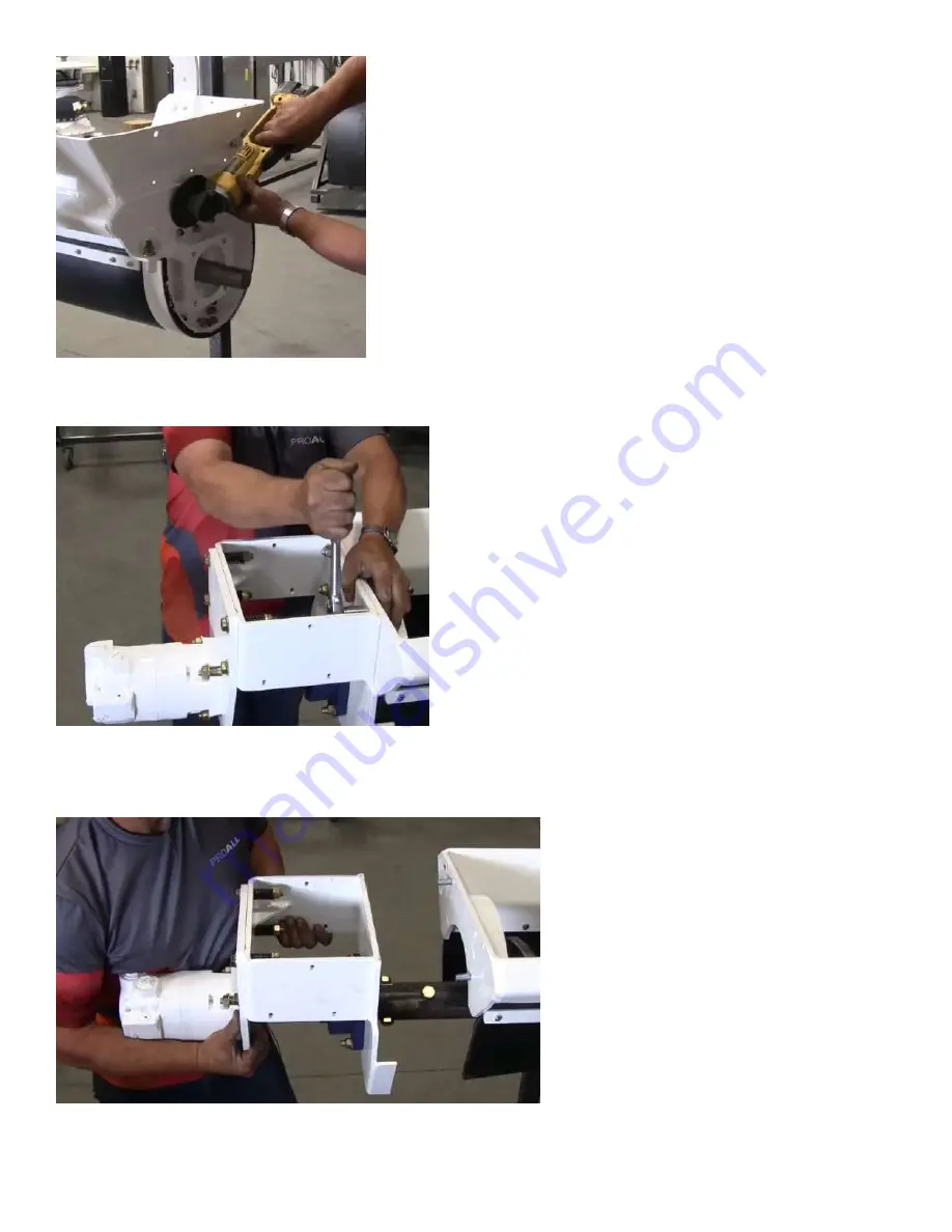
Figure 5. Remove idler shaft seal assembly bolts 

8.


Remove 4 bolts holding the offset bracket (PN MX10006) to the mix auger frame. 


Figure 6. Remove offset bracket from mix auger frame 

9.


Pull the motor, housing and auger assembly towards the top of the mix auger until the auger shaft clears the 
bottom of the mix auger frame. 


Figure 7. Separate mix auger from bottom of mix auger frame 

Summary of Contents for P Series

Page 1: ...1 PROALL Mobile Mixer Service Manual P Model MX04703 August 2020 Rev 1 0 ...

Page 2: ...2 5810 47 Avenue Olds Alberta Canada T4H 1V1 E info proallinc com P 403 335 9500 F 403 335 9560 ...

Page 3: ...VALVES 14 5 2 1 COIL REMOVAL 14 5 2 2 CARTRIDGE VALVE REMOVAL INSTALLATION 15 5 2 3 VALVE MANUAL OVERRIDES 16 5 3 HYDRAULIC CIRCUITS 17 5 3 1 DIAGNOSTICS 17 5 3 2 BELT 17 5 3 3 AUGER 18 5 3 4 CHARGE 19 5 4 MIXER FUNCTION DIAGNOSTICS 21 5 4 1 WATER 21 5 4 2 ADMIX 22 5 4 3 BELT 24 5 4 4 CEMENT 25 5 4 5 AUXILLARY 1 POZZOLAN 26 5 4 6 COLOR 27 5 4 7 MIX AUGER 28 5 4 8 BOOM CHUTE SWING 29 5 4 9 CHAIN OI...

Page 4: ...RING INSTALLATION 53 6 7 MOTOR INSTALLATION 56 6 8 WEAR PLATE REMOVAL AND INSTALLATION 58 7 CONVEYOR BELT SERVICE PROCEDURE 60 7 1 BELT INSTALLATION 60 7 2 BELT REMOVAL 65 7 3 BELT INSTALLATION ALTERNATE METHOD 65 7 4 LOOSEN THE CHAIN TENSIONER 66 7 5 TENSIONING THE CHAIN TENSIONER 67 8 CEMENT AUX FEEDER 69 8 1 DISCHARGE MAINTENANCE 69 8 2 SPEED SENSOR REPLACMENT 69 8 3 CHAIN MAINTENANCE 70 9 COLO...

Page 5: ...T 79 12 5 OIL LEVEL 80 12 6 OIL COOLER 80 12 6 1 FAN FUSES 80 12 6 2 FAN REMOVAL REPLACEMENT 81 12 6 3 TEMPERATURE SETTINGS 81 13 ELECTRICAL 82 13 1 RELAY AND FUSE REPLACEMENT 82 13 2 CANBUS NETWORKS 83 13 3 SUPPRESSION DIODES 84 14 APPENDIX 14 1 HYDRAULIC 14 1 1 SCHEMATIC 14 1 2 CONTROL VALVE LOCATIONS 14 1 3 PUMP SETUP 14 2 PNEUMATIC 14 2 1 SCHEMATIC 14 3 ADMIXTURE 14 3 1 SCHEMATIC 14 4 ELECTRIC...

Page 6: ...1 1 16 12 65 70 90 95 68 75 93 102 79 88 107 119 018 912 16 1 7 16 12 1 5 16 12 92 100 125 135 112 123 151 166 108 113 147 154 021 916 20 1 11 16 12 1 5 8 12 125 140 170 190 146 161 198 218 127 133 172 181 025 920 24 2 12 1 7 8 12 150 165 200 225 154 170 209 231 158 167 215 226 029 924 Note ORS hose ends and fittings on special request C61 FLANGE CHART Tube Size Fasteners O Ring 16 M10 x 1 5 17 de...

Page 7: ...5 220 3 4 225 165 390 290 540 400 7 8 230 170 570 420 880 650 1 345 225 850 630 1320 970 Torque figures indicated above are valid for non greased or non oiled threads and heads Therefore do not grease or oil bolts or cap screws unless otherwise specified When using locking nuts increase torque values by 5 Torque value for bolts and cap screws are identified by their head markings Bolt Diameter A B...

Page 8: ...amage to chain oiler pump seals and valves Proall recommends SAE 30 oil for the chain oiler For temperatures between 5 40 C 40 100 F For different environmental conditions refer to the list below SAE20 for Temperatures of 20 40 F SAE30 for Temperatures of 40 100 F SAE40 for Temperatures of 100 120 F SAE50 for Temperatures of 120 150 F Hydraulic fluid or red automatic transmission fluid are also ac...

Page 9: ...perator Panel E Air Pressure Regulator F Water Pump G Water Pump Strainer H Mixer Battery Power Connection A Hydraulic Valve Cabinet B Pressure Filters C Return Filter D Chain Oiler E Belt Tension Adjustment both sides F Oil Cooler G Hydraulic Pumps A B C D E F G H A B D C F E G ...

Page 10: ...ame time Aggregate materials are metered via gates at the outlet of the aggregate bin These materials are calibrated based on gate height in relation to belt counts The higher the gate height the more weight per belt count is metered The speed controlled functions operate based on RPM and counts The counts determine the volume output based on calibration and the RPM determines dosage or production...

Page 11: ... UP ON ITS OWN FLOW CONTROLLED FUNCTION INCREASES FLOW ON ITS OWN MIXER STOPS ON ITS OWN FUNCTION NOT TURNING NO ADMIX FLOW NO WATER FLOW MIXER SPEEDS ARE SLOW AND OR ERRATIC OIL TEMP ALARM IS ON NO POWER TO MIXER CHECK IF SPEED SENSOR IS ACTIVE CHECK IF SHOWING COUNTS AND OR RPM CHECK BELT PRESSURE IN DIAGNOSTICS CHECK AUGER PRESSURE IN DIAGNOSTICS CHECK IF ALL INSTALLED CANBUS DEVICES ARE ACTIVE...

Page 12: ...RESSURE CHECK VALVE SOLENOID INDICATOR CHECK OIL TEMPERATURE CHECK PTO IS ON CHECK AUGER VALVE RELIEF CHECK BELT VALVE RELIEF CHECK MASTER SWITH IS ON MANUALLY OVERRIDE VALVE REPLACE HYDRAULIC VALVE REPLACE SPEED SENSOR CLEAN OR REPLACE FLOW METER REPLACE SENSOR CABLE REPLACE CHECK VALVE ADJUST PUMP LOAD SENSE COMPENSATOR ...

Page 13: ...he first is the sensor and the second the magnet The magnet is threaded into the end of rotary shaft and the sensor measures via magnetic field the rotation of the shaft and converts this to a pulse and RPM output Electrical diagnostics All CANBUS speed sensors can be checked for operation on the Commander display Should an issue arise that points to a speed sensor not working the first step is to...

Page 14: ...L VALVES 5 2 1 COIL REMOVAL WARNING When installing cartridge valve coil nuts do not use pliers or any other hand tools to tighten These nuts only need to be hand tight Excessive tightening can stretch and distort the cartridge valve body causing the spool to stick Cartridge Valves To remove cartridge valve coil unplug the electrical cable and unscrew and remove coil nut and spacer Slide the coil ...

Page 15: ...to replace it right away Re fill reservoir to top up oil level if required Remove cartridge valve coil and electrical cable Loosen the cartridge using the appropriately sized socket or wrench for the cartridge hex It is highly recommended to use a deep socket to remove and replace the cartridges This will allow for much easier removal and replacement including proper re torqueing 10 size cartridge...

Page 16: ...out CCW until it stops If the override is left in even a little bit the function may creep or go into an alarm once in normal operation The mixer is designed to control these valves electrically only unless in an emergency Ensure locknut is hand tight and acorn nut is replaced Sectional Valves To manually override the mix auger section use a small Allen key and push down on override pin The more y...

Page 17: ...mp cement and any other auxiliary functions such as fly ash and color The belt function is the first function in the circuit with cement and auxiliary functions running in series after the belt The water pump is the only parallel function that runs with the belt and is independent of the belt operation When testing individual functions on the belt circuit it is best to run them independently using...

Page 18: ... IMPORTANT The auger hydraulic circuit is powered by the first load sensing piston pump that is referred to as the auger pump The auger circuit operates the mix auger boom chute s swing and chain oiler All the functions operate in parallel so each one can run independently of the other When testing individual functions on the auger circuit simply operate that function individually using the joysti...

Page 19: ...ned on this pressure will drop by as much as half the standby pressure This is normal as the charge pump makes up for system leakage through drain connections back to the reservoir The main return filter housing has special valving inside that ensures there is a positive pressure feeding the piston pumps The most important of these valves is the back pressure or charge relief valve Any oil not bei...

Page 20: ...20 has been removed and not replaced then the charge pressure will drop to zero C ...

Page 21: ...hecked quickly by pressing button 13 on the keypad to add water to the mix bowl Check the flow meter K Factor in the Sensor Calibration screen to ensure it isn t zero div by zero The default setting is 379 pulses gal 100 pulses litre Check the water strainer for build up that may be impeding the flow of water Check for loose inlet connections or any indication of air in water output Air will affec...

Page 22: ...flow This third mode must have both Admix Electric and Admix Auto de selected in Mixer Settings and Mixer Options Admix is flowing into mix bowl If the Commander system is showing an auto admix alarm then this is an indication that the output flow is not matching the set point flow Check to see if a green bar or digital reading is showing for flow If no flow reading is showing on the screen this i...

Page 23: ...he current draw is greater than 10000mA then the pump may be locked up If your mixer has diaphragm pumps disregard To unlock the pump loosen slightly the four Philips screws If the pump leaks you have gone too far See if the current draw goes down and pump starts turning Be careful not to loosen the screws to far you may lose the O ring seal behind the cover plate Once you get flow moving through ...

Page 24: ...matches the set point RPM when mixing see the CANBUS Speed Sensor section for more detailed troubleshooting Also confirm that the engine high idle speed is working properly If there is not enough flow from the belt pump then the belt will not meet it s setpoint If the oil temperature is not above 15 C 60 F and the belt is set for maximum speed then slow the belt speed down to 50 or warm up the sys...

Page 25: ... not work then there is something mechanically blocking jamming the function from turning 5 4 4 CEMENT If the Commander system is showing an auto cement alarm then this is an indication that the output speed is not matching the set point speed Check to see if the actual RPM is showing in Digital Readouts and that it matches the set point RPM when mixing see the CANBUS Speed Sensor section for more...

Page 26: ...to get the cement auger to turn If the cement auger still does not turn and the pressure is at compensator pressure of about 3600psi then the hydraulic valve may be stuck sticking To determine if the cement valve itself is the issue run the belt in belt unload mode and see if belt will turn or is at the same high pressure This is an indication that the cement valve is stuck blocking the flow of oi...

Page 27: ... primary cement metering system The color feeder also typically runs at much lower speed ratio then the cement so also be careful of low 10RPM setpoints If the speed setpoint is low increase your belt speed as high as you can This will increase the color speed setpoint at the same time The Commander control system will warn the mix design creator operator when the speed ratio goes below 15 by chan...

Page 28: ... lid switch alarm is active check for broken wires from lid switch back to the connection in the hydraulic valve I O 1 block port 8 Check fuse F17 If this fuse is blown it is very likely there is broken and shorted wire to the lid limit switch Check to see if the solenoid indicator light is ON Check the auger mix or auger reverse coil current in Electrical Diagnostics Is there current going to the...

Page 29: ...ping Tighten the lock nut Chute Tilt If the chute creeps down on its own when loaded the chute counterbalance valve needs to be adjusted Loosen the locknut with a 19mm wrench and turn the screw CW using an 8mm Allen key to increase the pressure setting until the chute stops creeping Tighten the lock nut Chute Extend Retract Special Version may not apply The chute extension circuit is shared with t...

Page 30: ... open first Also check the Electrical Diagnostics page and check the joystick indication light Is it green and is there a message saying Swing fault If there is a fault message then the joystick needs to be replaced You can use the wireless remote as a backup If electrically everything is okay and the manual overrides still do not allow the mix auger to swing then it is possible the rotary actuato...

Page 31: ...lution counter and start the lube system when the belt starts Confirm that the solenoid light is cycling on and off during the lube cycle The keypad button 6 will go from solid red to solid green when this is happening as well If electrically everything is working and still no lube oil is dispensed increase the pressure reducing valve pressure up by loosening the locknut with a 19mm wrench and adj...

Page 32: ...t the device must be replaced or sent back the manufacturer for repair Check to ensure there is power to the flow meter itself by looking at the indicator LED s on the top of the meter o The red LED is constantly lit to indicate that the flow meter is operational o The green LED blinks according to the frequency of the output signal o This blinking is not perceptible to the human eye at frequencie...

Page 33: ... ON OFF valve but it is also used for the cement aeration system and winter blow down Other optional functions like pneumatic fiber feeders can also be added If the water ON OFF valve is not working and there is no air to the mixer body make sure the air shut off valve is not closed Also ensure that the filter regulator pressure setting is at or above 75psi The regulator is equipped with an automa...

Page 34: ...ication 5 7 2 CONTINUITY AND CURRENT DRAW The current draw for individual functions can be found in the Electrical Diagnostics screen By touching the function name a green box will appear allowing the user to rotate the knob on the display and select the desired functions current output The output is shown in mA and is available to all functions that use variable output signals including higher cu...

Page 35: ...f the voltage setting does not show the correct voltage for the system press the default curves set button and see if it changes If it does not change reboot the Commander display by pressing the E Stop and waiting 3 4 seconds and restart Go back to the Mixer Settings and Maintenance screen and check the voltage setting again If it still reads the incorrect voltage call Proall as this may indicate...

Page 36: ...tivated The alarm cannot be removed until the wireless E Stop is reset Belt auto alarm This alarm indicates the control system cannot reach the RPM set point This alarm will stop the mixer The operator must acknowledge the alarm by pressing the belt button on the control knob 5 This will place the belt in open loop mode and the control system will ignore belt speed set points however the unit will...

Page 37: ...s is typically caused when batteries need to be replaced or the remote is too far away from the receiver If this alarm is activated the machine will stop The operator must acknowledge the alarm by pressing the belt button on the mixer control knob 5 The machine can then be run without the wireless Colour auto alarm This alarm indicates the control system cannot reach the set point This alarm will ...

Page 38: ...with the water valve controls then the operator can manually over ride the hydraulic valve and control the water flow using the manual water control valve at the back of the mixer Typical causes for this alarm are 1 The hydraulic system has not had sufficient time to become warm before high water flows can be achieved Reduce water flow requirement until operating temperature is achieved typically ...

Page 39: ... the operator has placed the system in automatic vibrator select mode Any of the four vibrators may be selected to automatically turn on with the belt Water ON is a warning message indicating that the operator has not turned the water on keypad button before running the belt in auto mode The mixer has been placed in belt unload mode by the operator Turn off by pressing button 10 on the keypad The ...

Page 40: ...uto alarm has been activated Cement is not meeting the RPM setpoint Is there an RPM reading Belt pressure AUTO COLOUR OFF RPM SENSOR Colour auto alarm has been activated Colour is not meeting the RPM setpoint Is there an RPM reading Belt pressure AUTO AUX1 OFF RPM SENSOR Aux1 auto alarm has been activated Aux1 is not meeting the RPM setpoint Is there an RPM reading Belt pressure AUTO AUX2 OFF RPM ...

Page 41: ...evel override has been activated Used to override cement bin low level water low level and gate material sensors to finish job POWDER CALIBRATION ON Reminder that powder calibration mode is active Belt will not run in the mode GATES CALIBRATION ON Reminder that gates calibration mode is active Cement will not run in this mode RPM HIGH ON FOR MIXING The high idle must be activated before mixing AUG...

Page 42: ...P ON FLASHING GREEN TO ARM Mix design calls for Admix2 and pump is not ON MAX ADMIX2 FLOW BELT SPEED LIMITED Belt speed is automatically limited if mixer operation is demanding more admix2 then the pump can deliver ADMIX1 PUMP ON FLASHING GREEN TO ARM Mix design calls for Admix1 and pump is not ON MAX ADMIX1 FLOW BELT SPEED LIMITED Belt speed is automatically limited if mixer operation is demandin...

Page 43: ...or equivalent 6 1 BOTTOM IDLER SHAFT SEAL AND BEARING REMOVAL Note when servicing idler shaft or idler shaft seal assembly only the motor does not need to be removed but can remain attached to the auger assembly For removal of the motor please see the 6 4 TOP MOTOR BEARING AND DRIVE SHAFT REMOVAL section Note To make removal easier support the auger screw with a crane or other lifting device throu...

Page 44: ...ing the idler shaft or mix auger frame are not damaged in the process b Using a chisel and mallet break the bearing housing apart c Using a torch cut the inner bearing race free from the shaft Figure 4 A cutting tool may be necessary to remove bearing 6 Remove the auger seal PN AGSL005A bearing seal assembly PN REJ432 and auger seal PN AGSL005 from the idler shaft 7 Remove the bolts holding the id...

Page 45: ...acket PN MX10006 to the mix auger frame Figure 6 Remove offset bracket from mix auger frame 9 Pull the motor housing and auger assembly towards the top of the mix auger until the auger shaft clears the bottom of the mix auger frame Figure 7 Separate mix auger from bottom of mix auger frame ...

Page 46: ... Cut the welded portion of the idler shaft pin PN MX03261 and remove 13 Remove the idler shaft PN RE3314 inner seal PN AGSL001D inner cover plate PN REJ591 and retaining ring PN REJ315 6 2 BOTTOM IDLER SHAFT AND SEAL INSTALLATION 1 With the wear plate PN REJ426 on a flat surface place the spacer ring PN REJ593 over the wear plate aligning the bolt holes 2 Grease both surfaces of the flat disk on t...

Page 47: ... holes through all seal parts and using two bolts one on either side of the idler shaft align the stack together Figure 11 Use two bolts to align seal assembly 7 From the inside of the mix auger frame orient the seal assembly so the slotted hole in the wear plate is towards the upper side of the mix auger and aligns with the grease hole in the bottom of the mix auger frame Install the seal assembl...

Page 48: ...auger frame 8 Install the remaining bolts so the inner rubber seal PN AGSL001D just compresses 9 Once installed turn the auger shaft by hand to ensure the shaft spins easily A small amount of side movement is expected 10 Place anti seize compound on the idler shaft to help prevent rust buildup and ease future removal of the shaft from the auger tube ...

Page 49: ...x auger tube with the holes in the idler shaft and slide the mix auger onto the idler shaft 12 Using a rod or drift align the holes in the auger with the idler shaft and install a shaft bolt PN 1261817 233111 into the hole farthest from the bottom bearing This bolt is close in size to the hole and may need to be tapped in with a hammer Figure 15 Use rod or drift to align holes in shaft and auger ...

Page 50: ...pin farthest from the bottom bearing Welding both ends of the pin or completely around the end of the pin will make it difficult to extract the pin in future service intervals Figure 17 Weld pin closest to the bottom bearing 6 3 BOTTOM BEARING INSTALLATION 1 Place a bead of silicone in one continuous ring around the center of both sides of the auger seal PN AGSL005 and slide over the idler shaft P...

Page 51: ...y over the shaft ensuring the grease hose hole in the outer edge of the bearing seal assembly is oriented towards the upper right hand side of the mix auger Slide the assembly over the shaft contacting the auger seal Figure 19 Install bearing seal assembly 4 Install the auger seal AGSL005A over the shaft 5 Loosen the collar of the bearing PN AGBR006 and orient the grease fitting hole to the right ...

Page 52: ...o install the coupling with a small amount of torque as the grease hose fittings may split when too much torque is applied 6 4 TOP MOTOR BEARING AND DRIVE SHAFT REMOVAL Note To make removal easier support the auger screw with a crane or other lifting device throughout the following procedure 1 Remove the top shield PN MX01846 and bottom shield PN MX01795 from the offset bracket PN MX10006 2 Remove...

Page 53: ...portion of the drive shaft PN MX01389 with bolt holes and slide the shaft into the auger tube Install the 2 shaft bolts PN 1261718 233111 Figure 21 Place anti seize on drive shaft Figure 22 Install shaft bolts 2 Install the offset bracket with 4 bolts PN 119162 387708 233108 ...

Page 54: ...23 Install offset bracket 3 Remove the bearing collar from the bearing PN AGBR004A Figure 24 Remove bearing collar 4 Remove the insert from the bearing and place on the drive shaft Figure 25 Remove bearing insert ...

Page 55: ...stalling bearing with grease nipple facing upwards 6 Install the carriage bolts with the head inside the mix auger frame and the nuts at the bearing side loose so the bearing is free to move along the face of the offset bracket 7 Install the bearing collar by hand then using a collar wrench or punch and mallet tighten the collar until resistance is felt then turn the collar another turn ...

Page 56: ...s in the bearing 6 7 MOTOR INSTALLATION 1 Place grease on the splines of the drive shaft PN MX01389 and motor shaft PN HYMT009 Figure 29 Place grease on drive shaft splines Figure 30 Place grease on motor splines 2 Install splined coupling PN MX00017 on drive shaft ...

Page 57: ...8 x2 233108 through the mount plate and offset bracket then place a compression spring PN 347212 over each bolt and secure with washers and nuts Tighten the nut on each bolt until each spring is compressed to 1 3 8 inch Figure 32 Compress springs to 1 3 8 inch 6 Using a pry bar ensure the splined coupling moves freely between the drive shaft and motor This indicates the auger is centered in the mi...

Page 58: ...ew flighting is within 1 8 inch In general wear plate replacement should take place before the auger flighting shows signs of wear Note The auger screw should be replaced when the distance between the outer edge of the auger flighting and bolt HOLE is within 1 8 inch When the auger flighting has worn to the bolt holes the entire auger screw will need to be replaced PN MX10803 Figure 34 Worn auger ...

Page 59: ...ble without having to replace the stir tabs 1 Remove the mix auger screw from the mix auger using the 6 1 BOTTOM IDLER SHAFT SEAL AND BEARING REMOVAL and 6 4 TOP MOTOR BEARING AND DRIVE SHAFT REMOVAL procedures outlined above 2 Cut the bolts off the wear plates and stir tabs using a cutting wheel or torch Note Ensure the orientation of the replacement wear plates and stir tabs matches the replaced...

Page 60: ...e above the other on the rear of the mixer 3 Remove the old belt from the new and continue the installation of the new belt from step 11 in the 7 1 BELT INSTALLATION procedure 2 7 4 LOOSEN THE CHAIN TENSIONER 3 Use a spacer between the belt and frame this can be 1 inch round bar oriented and temporarily attached to the mixer frame as shown for both sides of the belt Figure 37 This spacer is made o...

Page 61: ...e belt hydraulics to install the belt engage the drive in the reverse direction to feed the belt into the mixer 8 When the belt appears at the front of the mixer remove the bolts holding the links above the belt Figure 41 Remove bolts holding the chain links at this stage of the procedure 9 Wrap the belt around the belt sprockets and feed the belt back into the mixer pushing the belt periodically ...

Page 62: ... even one above the other on the rear of the mixer Figure 43 Belt lacing ends 11 Using a pry bar pry the bottom belt towards the rear of the mixer Figure 44 Pry using pry bar and the mixer frame 12 Ensure the chain rollers are resting on both the upper and lower chain guides Adjust if necessary until the chain rollers are resting on the guides ...

Page 63: ...oth sides of the belt lacing including the link plates and cotter pins Figure 47 Install coupling links next to belt lacing 14 Using a ratchet strap place the strap around the ends of the belt and attach the strap to the bin body such as the last gusset on the aggregate bin Ensure the strap is offset from the edge of the belt by about 4 inches ...

Page 64: ...tom links towards rear of the mixer 16 Tighten the ratchet strap to bring the lacing teeth together and insert the lacing bar into the lacing Figure 50 Tighten ratchet strap and bring upper and lower lacing teeth together along with lacing bar 17 Hammer the lacing bar into the lacing until the bar reaches through the lacing teeth entirely The bar will zip the lacing together as it is pounded in ...

Page 65: ...he section 7 3 Belt installation alternate METHOD otherwise proceed with the following section for belt removal 1 Remove the mix auger and mix bowl 2 Rotate the belt so the belt lacing is facing the rear of the mixer 3 Cut the belt lacing and remove the coupling chain links at the lacing 4 Using the belt hydraulics run the upper portion of the belt off the rear of the mixer completely allowing the...

Page 66: ...the belt into the mixer until the ends of the belt are even one above the other on the rear of the mixer 10 Remove the old belt from the new and continue the installation of the new belt from step 11 in the 7 1 BELT INSTALLATION procedure 7 4 LOOSEN THE CHAIN TENSIONER 1 Loosen the nut on the threaded shaft next to the bearing to allow the shaft to rotate Figure 53 Loosen bearing nut 2 Loosen the ...

Page 67: ...ure the nut holding the end of the threaded rod to the bearing does not come off the threaded rod during this procedure Figure 56 Loosen chain tensioner 7 5 TENSIONING THE CHAIN TENSIONER 1 Loosen the nut on the threaded rod that is touching the bearing guide until the nut touches the drive end nut on the threaded rod Tighten this nut to keep it from wandering on the threaded rod Figure 57 Adjust ...

Page 68: ...inch or 6mm of space between the spring tube and the washer when the tube is held against the bearing guide Figure 58 Adjust spring nut 3 Secure the threaded rod to the bearing by tightening the nut in the bearing against the lock washer on the threaded rod Figure 59 Secure bearing nut ...

Page 69: ...nspect inside the cement discharge throat to make sure it is free can clear of hardened cement powder as well 8 2 SPEED SENSOR REPLACMENT Remove bolts top and bottom to allow sensor mounting plate to be removed Disconnect sensor wire and remove wire from clamp Remove sensor bolts from mounting plate and old sensor can now be replaced with the new sensor Make sure when mounting the new sensor that ...

Page 70: ...nce between the shafts Inspect the chain oiler brush for wear and that it is oiling the chain If tension is good tighten up bolts 9 COLOR FEEDER 9 1 SPEED SENSOR REPLACEMENT To replace the speed sensor remove sensor bracket nut and slide the bracket off the bolt Unplug the speed sensor cable and remove sensor mounting bolts Install the new speed sensor and re position the mounting bracket so that ...

Page 71: ...erly tensioned and tighten the bolt Manually lubricate the chain before replacing the cover Inner Chain To replace or tighten the inner chain loosen the two bolts to allow the motor mounting plate to slide forward When replacing the chain or adjusting the tension ensure that the chain deflection is approximately 2 4 of the centerline distance between the shafts To tension the chain slide pry the m...

Page 72: ...allow the water to flow through to the outlet Turn off the water outlet when air in the line is gone and flow reading are stable 10 2 STRAINER CLEANING AND REPLACEMENT IMPORTANT A dirty water strainer will cause the Commander control system to speed up the water pump when in auto mode which will eventually cause it to go into a fault if it can t meet its water flow target Check the water strainer ...

Page 73: ...ow meter use a non metal pipe cleaning brush or a lint free cloth 11 ADMIX 11 1 PRIMING THE SYSTEM IMPORTANT The admix lines must be primed before mixing Air in the lines will cause false readings from the flow meters and delay the admix flow into the mix bowl on start up To prime the admix pumps first ensure the outlet ball valves are in the off zero position This cycles the fluid straight back t...

Page 74: ...mix pump when in auto mode which will eventually cause it to go into a fault if it can t meet it s admix flow target Check the admix strainer regularly for buildup To remove and inspect the admix inlet strainer unthread the bowl and pull the strainer out of the housing Be careful not to lose the seal Clean the strainer as necessary ensuring all debris is removed and outer mesh is clean Clean and d...

Page 75: ... system with water weekly will help prevent this buildup To remove the flow meter uncouple union fitting and remove the hose and gear clamp Disconnect the electrical wire If removing more than one flow meter for cleaning be careful not to mix up the wires when re installing To clean the flow meter run a non metal pipe cleaner through the flow meter several times to clean any debris or build up ins...

Page 76: ... belt pump compensator using a 13mm wrench With belt unload activated adjust the pressure to 3900psi using a 3mm Allen Key Activate belt unload by pressed button 10 and then button 14 on the keypad Turn the relief valve adjustment out until the pressure on the display starts to drop below 3900psi You should here the engine load up as well Turn the relief valve back until the display reads 3900psi ...

Page 77: ... Allen key Loosen the lock nut on the auger pump pressure compensator using a 13mm wrench With the chute tilt cylinders bottomed out adjust the auger pump pressure compensator to 3900psi using a 3mm Allen key Release chute tilt function Tighten the lock nut With the chute tilt cylinders bottomed out again adjust the load sense relief until the pressure reads 3600psi Release chute tilt function Tig...

Page 78: ...n filter bowl and filter head particular attention must be given to the threads 5 Examine filter especially sealing surfaces for mechanical damage 6 Check O rings and replace if necessary Bowl O Ring 67 95 x 2 62 Replacing the element 1 Wet the sealing surfaces and thread on the filter head and bowl as well as the O ring with clean operating fluid 2 When fitting a new filter element check that the...

Page 79: ... need to be removed completely Remove the diaphragm and safety filter assembly Remove the filter element Collect the spent oil and cartridge in a suitable container and dispose of them in compliance with statutory legislation Replacing the element Lubricate the filter element seal and diaphragm seal with the operating fluid Fix the element on the diaphragm Insert the element back into the bowl Che...

Page 80: ...OOLER WARNING The hydraulic oil cooler operation is critical in ensuring oil temperature is keep under 70 C 160 F Ensure cooler core is not plugged with debris and fans are running If oil temperature rises abnormally or is going into temperature alarm check to ensure fans are on 12 6 1 FAN FUSES Oil cooler fans can be turned on manually on the Mixer Settings screen by pressing Cooler ON This is a ...

Page 81: ... fuses constantly the motor may be shorted Replace the fan 12 6 3 TEMPERATURE SETTINGS Depending on the ambient temperature conditions it may be necessary to adjust the cooler on and off settings The cooler on temperature needs to be higher than the off temperature Generally the cooler on temperature is set for between 40 50 C 104 122 F and the off to between 32 40 C 90 104 F In hot ambient condit...

Page 82: ... Admix 2 Flow Meter Selection Admix 3 Flow Meter Selection J1939 Network Supply I O 1 Hydraulic Controls 1 I O 2 Hydraulic Controls 2 I O 3 Flow Meters Printer Display Box Water Flow Meter Selection Charge Cradle PLC Supply PLC Supply Outputs 1 PLC Supply Outputs 2 PLC Supply Outputs 3 PLC Supply Outputs 4 PLC Aux Power Supplies Cooler Fan Type Selector Brushless Brushed Selector Fuse Autolube Opt...

Page 83: ...S resistance you should have a total of 60ohms nominal between the CAN H and CAN L terminals when the power is off A range of 55 65ohms is typical There are CAN resistors inserted on the circuit board that serve as the start of the network for CAN 1 2 and 3 The CAN2 end terminating resistor is in the M12 CAN splitter block mounted inside the hydraulic valve cabinet The CAN3 and PRINTER CAN end ter...

Page 84: ...after install simply remove the associated suppression diode and try again If the fuse is good then replace the suppression diode Fuse AF4 is the main power feed for all CAN J1939 input devices on the mixer eg Belt and cement speed encoders If multiple sensors are down check your fuse Fuse F10 is the main power feed to the display The display will not turn on if this fuse is blown INFORMATION The ...

Page 85: ...International Manufacturing Inc P P1 OUT IN OUT IN 2 1 3 IN S1 S2 2 1 3 OUT IN ...

Page 86: ...MATION IT DISCLOSES ARE CONFIDENTIAL PROPERTIES OF PROALL INTERNATIONAL MFG INC AND MAY NOT BE REPRODUCED OR DISCLOSED TO OTHERS OR USED FOR THE MANUFACTURE OR OTHER PURPOSES WITHOUT PRIOR CONSENT THIS DRAWING SHALL BE RETURNED TO PROALL INTERNATIONAL MFG INC UPON REQUEST DIAMETRICAL 1 64 REV A International Manufacturing Inc B B WATER VALVE BELT VALVE BELT BYPASS VALVE RELIEF 3900 PSI AUX VALVE L...

Page 87: ...E E F F AUGER MIX COIL AUGER REVERSE COIL BOOM DOWN COIL CHUTE DOWN COIL SWING LEFT COIL CHAIN OILER OUT AUGER PRESSURE PUMP BELT MANIFOLD DRAIN HECO DRAIN BELT PUMP IN CEMENT VALVE CEMENT OUT WATER VALVE BOOM UP COIL CHUTE UP COIL SWING RIGHT COIL SEE NOTE B SEE NOTE A AUX OUT AUX RETURN NOTE A MANUAL OVER RIDE REMOVE ACORN NUT AND ADJUST HEX SCREW IN TO FORCE VALVE OPEN CONTINUE TO TURN IN TO AD...

Page 88: ...RAWING AND THE INFORMATION IT DISCLOSES ARE CONFIDENTIAL PROPERTIES OF PROALL INTERNATIONAL MFG INC AND MAY NOT BE REPRODUCED OR DISCLOSED TO OTHERS OR USED FOR THE MANUFACTURE OR OTHER PURPOSES WITHOUT PRIOR CONSENT THIS DRAWING SHALL BE RETURNED TO PROALL INTERNATIONAL MFG INC UPON REQUEST DIAMETRICAL 1 64 REV A International Manufacturing Inc AUGER PUMP LOAD SENSE RELIEF 3600 PSI SWING LEFT COI...

Page 89: ...6 NTS VIEW D D THIS DRAWING AND THE INFORMATION IT DISCLOSES ARE CONFIDENTIAL PROPERTIES OF PROALL INTERNATIONAL MFG INC AND MAY NOT BE REPRODUCED OR DISCLOSED TO OTHERS OR USED FOR THE MANUFACTURE OR OTHER PURPOSES WITHOUT PRIOR CONSENT THIS DRAWING SHALL BE RETURNED TO PROALL INTERNATIONAL MFG INC UPON REQUEST DIAMETRICAL 1 64 REV A International Manufacturing Inc WATER PUMP OUT BELT OUT BELT RE...

Page 90: ...THIS DRAWING AND THE INFORMATION IT DISCLOSES ARE CONFIDENTIAL PROPERTIES OF PROALL INTERNATIONAL MFG INC AND MAY NOT BE REPRODUCED OR DISCLOSED TO OTHERS OR USED FOR THE MANUFACTURE OR OTHER PURPOSES WITHOUT PRIOR CONSENT THIS DRAWING SHALL BE RETURNED TO PROALL INTERNATIONAL MFG INC UPON REQUEST DIAMETRICAL 1 64 REV A International Manufacturing Inc HECO DRAIN SWING RIGHT COIL CHUTE UP COIL BOOM...

Page 91: ...16 PGN 25 Jan 16 NTS VIEW F F THIS DRAWING AND THE INFORMATION IT DISCLOSES ARE CONFIDENTIAL PROPERTIES OF PROALL INTERNATIONAL MFG INC AND MAY NOT BE REPRODUCED OR DISCLOSED TO OTHERS OR USED FOR THE MANUFACTURE OR OTHER PURPOSES WITHOUT PRIOR CONSENT THIS DRAWING SHALL BE RETURNED TO PROALL INTERNATIONAL MFG INC UPON REQUEST DIAMETRICAL 1 64 REV A International Manufacturing Inc CEMENT CHAIN OIL...

Page 92: ...E REPRODUCED OR DISCLOSED TO OTHERS OR USED FOR THE MANUFACTURE OR OTHER PURPOSES WITHOUT PRIOR CONSENT THIS DRAWING SHALL BE RETURNED TO PROALL INTERNATIONAL MFG INC UPON REQUEST DIAMETRICAL 1 64 REV A International Manufacturing Inc Rexroth 71 45 25 Pump LOAD SENSE INLET 250 PSI 17 bar 3600 PSI 248 bar PUMP LOAD SENSE ADJUSTMENT PUMP PRESSURE COMPENSATION ADJUSTMENT CASE DRAIN OUTLET OUTLET OUTL...

Page 93: ...TLE SIZE SCALE REV 1 1 A PROALL INC B P MODEL PNEUMATIC MIX WATER CIRCUIT 4 24 2019 Curtis Steele REVISION HISTORY REV DESCRIPTION DATE APP A INITIAL ISSUE 4 24 2019 WATER PUMP MIX WATER MIX BOWL AIR SUPPLY FIBRE FEEDER WATER MANUAL 7PSI OPTIONAL AERATOR ...

Page 94: ...AM 8 24 2018 Curtis Steele REVISION HISTORY REV DESCRIPTION DATE APP A INITIAL ISSUE 4 14 2020 1 2 1 2 1 2 ADMIX MANUAL FM1 BYPASS1 INLET1 FM2 INLET2 BYPASS2 FLOW METER CABINET FM1 FM2 AIR INLET WATER PUMP MIX WATER CLEAN OUT WATER FILTER FILTER PUMP PUMP 0 5 0 5 10 GALLON 20 GALLON AIR BLOW DOWN ...

Page 95: ...n OH 45415 United States Phone 1 937 415 7700 PROALL X2 X31 AF13 F8 F7 F4 F6 F5 K1 K4 K5 K8 K10 F34 F22 F26 F27 F31 F32 F33 F11 F2 AF29 AF30 AF4 F10 F12 F17 F18 F19 F20 F21 AF5 AF6 AF7 AF8 AF9 F1 F3 F9 F13 F14 F15 F16 AF28 F23 F24 F25 K2 K3 K7 K9 K11 X10 X9 X18 X13 X27 X28 X29 X30 X14 X7 X12 X17 X5 X8 X1 X4 X26 X25 X24 X23 X22 X21 X20 X19 X3 X6 X11 X15 X16 K6 331mm 133mm 114mm 85mm 357mm 102mm 114...

Page 96: ... F16 2 F21 2 F19 2 F21 2 F19 2 F18 2 F18 2 F20 2 F20 2 K2_87 K2_87 K6_86 86 85 K1A WTRHTRPMP_2 AF9_AuxV 5_15A AF9 F8_30A_SP2 F8 F7_30A_SP1 F7 F4_30A_HeatExch F4 F2_2A_RPM F2 F12_5A_PLC F12 AF4 2 K4_86 F7 2 F7 2 F6 2 F6 2 86 85 K3A HighLevelRly_2 12 24V_Batt3 K3_87 K3_87 F2 2 F2 2 K2_86 K3_86 K3_86 Max Torque 3 9Nm 1 X31 1 Diameter 3 6mm X28 Cooler 1 Negative F9 2 F9 2 F8 2 F8 2 F5 2 F5 2 F10 2 F10...

Page 97: ...att3 K8_87 K8_87 K8_86 K8_86 86 85 K8A SPARE 2_30A_2 F8 2 F8 2 12 24V_Batt3 K5_86 K5_86 K5_87 86 85 K5A COOLER 2 F6 2 F6 2 Diameter 3 6mm 1 X29 Cooler 2 12 24V 12 24V_Batt3 K10_87 K10_87 86 85 K10A SPARE_30A_2 F7 2 F7 2 K10_86 K10_86 86 85 K9A RPMRLYPCM_2 K9_86 K9_86 12 24V_Batt3 K9_87 K9_87 K9_30 K9_30 K9_87a K9_87a 12 24V_Batt3 F22 40 F22 17 F22 3 F31 17 F31 3 F31 40 F32 40 F32 17 F32 3 F33 40 F...

Page 98: ...3 4 5 6 X7 INPUTS_2 1 2 3 4 5 6 7 8 X12 AX14_AX21 4 2 1 10 5 7 8 6 3 9 X5 OUTPUTS 1 2 3 4 5 6 7 8 9 10 X8 V 1 2 3 4 5 6 7 8 9 10 11 12 X4 INPUTS_1 9 18 7 4 5 13 10 12 14 8 2 6 15 1 11 17 16 3 19 20 21 22 23 24 25 X11 IO_ 1 1 18 2 13 8 5 7 11 14 4 16 10 6 12 15 3 17 9 IO_ 2 X10 1 18 2 5 6 9 11 12 14 15 3 8 13 16 7 10 19 4 17 20 21 X9 IO_ 3 14 5 12 11 10 15 7 3 9 2 4 6 13 8 1 17 16 18 19 20 21 22 23...

Page 99: ...15 27 X15 28 X4 3 X7 3 X7 2 X15 3 X15 4 X15 5 X15 6 X15 7 X15 8 X4 11 X4 12 F22 3 F31 3 F32 3 F33 3 F26 3 X7 5 X15 25 X4 4 X4 5 X4 6 X4 7 X7 4 X15 23 X15 24 X4 10 X7 1 X4 8 X4 9 X5 6 X16 9 X16 10 X16 11 X16 12 X16 13 X16 14 X16 15 X16 16 X16 17 X16 18 X16 19 X16 20 X16 21 X16 22 X16 23 X16 24 X16 25 X16 26 X16 2 X16 3 X3 9 X5 2 X16 6 F34 3 F34 3 K9_86 K9_86 X18 1 X18 2 X18 3 X18 4 X18 7 X18 1 X18 ...

Page 100: ... ADMIX 1 ADMIX 2 WORK LIGHTS ...

Page 101: ... COOLER 1 VIB1 SPARE VIB1A SPARE VIB2A VIB2 VIB3 VIB4 VIB5 ...

Page 102: ... V 5A V V FLOW METER V FLOW METER V FLOW METER V FLOW METER V FLOW METER WATER FLOW ADMIX1 FLOW ADMIX2 FLOW ADMIX 3 FLOW ADMIX 4 FLOW WATER ON WATER LEVEL FIBRE LATEX ON CEMENT LOW ADMIX AUX ...

Page 103: ... V 5A V AUGER MIX AUGER REV BOOM UP BOOM DN CHUTE UP CHUTE DN SWING RIGHT SWING LEFT WATER PUMP AUGER PSI BELT BELT PSI BELT BYPASS CHAIN OILER CEMENT AUGER SAFETY ...

Page 104: ... V 5A V COLOUR CEMENT HIGH AUX1 AUX2 BOOM LIMIT LATEX AUX1 HIGH AUX1 LOW MAT A TEACH MAT A DETECT MAT B TEACH MAT B DETECT REMOTE ESP OUT REMOTE ESP IN SPARE SPARE ...

Page 105: ... BATTERY V BATTERY V ...

Page 106: ... CAB MST SW IN TRUCK IGN OUT CHARG CRDL V PRINTER CAN L CAB MST SW IN TRUCK IGN OUT CHARG CRDL V PRINTER CAN H PRINTER V PRINTER V AUTO LUBE V RPM2 RPM1 TRUCK IGN IN RPM3 ENGINE E STOP AUTO LUBE V ...

Page 107: ... DISP V BATT V V CANOPEN H CANOPEN L PRT CAN H PRT CAN L J1939 H J1939 L E STOP IN CAB MST OUT TRUCK IGN OUT WL SW IN AUTO STOW SW SPARE SPARE SPARE SPARE SPARE SPARE SPARE ...

Page 108: ...3 42 25 FT 16AWG RED 105C 300V UL1007 1569 PVC CSA TR 64 ROHS 4 42 25 FT 16AWG YELLOW 105C 300V UL1007 1569 PVC CSA TR 64 ROHS 5 42 25 FT 34 522 200M SPLIT LOOM FLEX CONDUIT 3 8Inch 200Mtr 6 35 5 FT 34 521 30M SPLIT LOOM FLEX CONDUIT 0 25INCH 30MTR 7 14 LABEL WHITE HEATSHRINK LABEL 1 2 3 4 5 1 5 2 1 3 2 1 2 3 4 5 6 7 8 9 10 11 12 4 6 1 3 2 4 1 6 2 1 6 2 1 6 2 1 6 2 1 6 2 1 6 2 1 6 2 16 AWG YEL 16 ...

Page 109: ... 300V WHITE 4 3 5 FT 18AWG YELLOW WIR 18G 16 30ST UL 1569 1007 300V YEL 5 12 FT 18AWG ORG WIR 18G 16 30ST UL 1569 1007 300V ORG 6 72 FT 34 521 30M SPLIT LOOM FLEX CONDUIT 0 25INCH 30MTR 7 1 DT04 6P DEUTSCH DT SERIES RECPETACLE 6 PIN 8 1 W6P LOCKING WEDGE RECEPTACLE 6P DEUTSCH 9 6 0460 202 16141 CONTACTS SOLID CRIMP TYPE 16 20AWG PIN 10 1 114017 DEUTSCH DT SERIES SEALING PIN 11 16 LABEL WHITE HEATS...

Page 110: ...0ST UL 1569 1007 300V ORG 8 31 FT 16AWG BLACK WIR 16G 26 30ST UL1007 BLACK 9 31 FT 16AWG WHITE 105C 300V UL1007 1569 PVC CSA TR 64 ROHS 10 261 FT 34 522 200M SPLIT LOOM FLEX CONDUIT 3 8Inch 200Mtr 11 1 DT06 6S DEUTSCH DT SERIES PLUG 6 SOCKET 12 1 W6S LOCKING WEDGE RECEPTACLE 6P DEUTSCH 13 6 0462 201 16141 DEU CONTACT SIZE16 CRIMP TYPE 16 18G F 14 1 114017 DEUTSCH DT SERIES SEALING PIN 15 19 LABEL ...

Page 111: ...ONTINUITY AND SHORTS Electronic Supply Ltd 1 ft 1 ft 5 ft IPC TOLERANCE UNLESS OTHERWISE SPECIFIED 1 in 0 in 2 in 0 in 5 ft 10 ft 4 in 0 in 10 ft 25 ft 6 in 0 in 25 ft 5 0 in S CC25047 183146 Pro All DISPLAY 25 WAY BLUE X3 0 TABLOID 1 1 T P1 U V 2 SALES PERSON QUANTITY N A B C D E F G H J K L M P R S T U V W X W X NOTES 1 STRIP OFF THE ENTIRE JACKET OF ITEM 1 2 APPLY INDIVIDUAL HEATHRINK ON SOLDER...

Page 112: ...ured IAW IPC WHMA A 620 ASSEMBLY TESTED FOR HIPOT CONTINUITY AND SHORTS Electronic Supply Ltd 1 ft 1 ft 5 ft IPC TOLERANCE UNLESS OTHERWISE SPECIFIED 1 in 0 in 2 in 0 in 5 ft 10 ft 4 in 0 in 10 ft 25 ft 6 in 0 in 25 ft 5 0 in CC25048 183139 Pro All CAB 25 WAY BLACK X3 0 TABLOID 1 1 P1 SALES PERSON QUANTITY RED BLK GRN BLK RED ORG BLK WHT BLK GRN BLK BLU RED BLK WHT GRN WHT BLU WHT RED WHT BLU BLK ...

Page 113: ... INCHES IMPERIAL UNLESS OTHERWISE STATED THIS INFORMATION IS CONFIDENTIAL AND DISCLOSED TO YOU ON CONDITION THAT NO FURTHER DISCLOSURE IS MADE WITHOUT AUTHORIZATION FROM MRO QTY ITEM Manufactured IAW IPC WHMA A 620 ASSEMBLY TESTED FOR HIPOT CONTINUITY AND SHORTS Electronic Supply Ltd 1 ft 1 ft 5 ft IPC TOLERANCE UNLESS OTHERWISE SPECIFIED 1 in 0 in 2 in 0 in 5 ft 10 ft 4 in 0 in 10 ft 25 ft 6 in 0...

Page 114: ...OR HIPOT CONTINUITY AND SHORTS Electronic Supply Ltd 1 ft 1 ft 5 ft IPC TOLERANCE UNLESS OTHERWISE SPECIFIED 1 in 0 in 2 in 0 in 5 ft 10 ft 4 in 0 in 10 ft 25 ft 6 in 0 in 25 ft 5 0 in CC25050 183142 Pro All IO 1 25 WAY GRAY X3 0 TABLOID 1 1 P1 2 SALES PERSON QUANTITY NOTES 1 STRIP OFF THE ENTIRE JACKET OF ITEM 1 2 APPLY INDIVIDUAL HEATHRINK ON SOLDER CUPS 2 A LABELS 5 19 20 21 22 23 24 25 1 2 3 4...

Page 115: ...ST NAME SIZE DESCRIPTION MATERIAL P N SUB VER REV NO DATE DESCRIPTION DRN DIMENSIONS ARE IN INCHES IMPERIAL UNLESS OTHERWISE STATED THIS INFORMATION IS CONFIDENTIAL AND DISCLOSED TO YOU ON CONDITION THAT NO FURTHER DISCLOSURE IS MADE WITHOUT AUTHORIZATION FROM MRO QTY ITEM Manufactured IAW IPC WHMA A 620 ASSEMBLY TESTED FOR HIPOT CONTINUITY AND SHORTS Electronic Supply Ltd 1 ft 1 ft 5 ft IPC TOLER...

Page 116: ...ft 6 in 0 in 25 ft 5 0 in CC25052 183145 PRO ALL VIB COOLER PNL MNT X3 1 TABLOID 1 1 N P A B C D E F G H I J K L M O P1 SALES PERSON QUANTITY OPEN END A B C D E F G H I J K L M O P N SECTION A A A A P1 NON MOLDED NOTES 1 APPLY INDIVIDUAL HEATHRINK ON SOLDER CUPS 2 TAG HOOK UP WIRES WITH LABELS ITEM 8 AS SHOWN 1 6 5 RED 14AWG BLK 14AWG ITEM 1 TO ITEM 4 GASKET COOLER 1 COOLER 1 VIBRATOR 1 GROUND 2 X...

Page 117: ...EVISION SHEET NO OF DRAWING NO CUST P N DESCRIPTION CUST NAME SIZE DESCRIPTION MATERIAL P N SUB VER REV NO DATE DESCRIPTION DRN DIMENSIONS ARE IN INCHES IMPERIAL UNLESS OTHERWISE STATED THIS INFORMATION IS CONFIDENTIAL AND DISCLOSED TO YOU ON CONDITION THAT NO FURTHER DISCLOSURE IS MADE WITHOUT AUTHORIZATION FROM MRO QTY ITEM Manufactured IAW IPC WHMA A 620 ASSEMBLY TESTED FOR HIPOT CONTINUITY AND...

Page 118: ...R DISCLOSURE IS MADE WITHOUT AUTHORIZATION FROM MRO QTY ITEM Manufactured IAW IPC WHMA A 620 ASSEMBLY TESTED FOR HIPOT CONTINUITY AND SHORTS Electronic Supply Ltd 1 ft 1 ft 5 ft IPC TOLERANCE UNLESS OTHERWISE SPECIFIED 1 in 0 in 2 in 0 in 5 ft 10 ft 4 in 0 in 10 ft 25 ft 6 in 0 in 25 ft 5 0 in CC25066 183141 PRO ALL BATTERY INETRNAL PNL MOUNT X2 0 TABLOID 1 1 BLK OPEN END P1 SECTION A A A A P1 2 N...

Reviews: