Revision 01/2018 EN
PRIMES
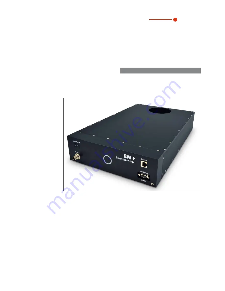
BeamMonitor BM+
BM+ 60, BM+ 100
LaserDiagnosticsSoftware LDS 2.98
Translation of the original instructions
Operating Manual
Page 1: ...Revision 01 2018 EN PRIMES BeamMonitor BM BM 60 BM 100 LaserDiagnosticsSoftware LDS 2 98 Translation of the original instructions Operating Manual...
Page 2: ......
Page 3: ...IMPORTANT READ CAREFULLY BEFORE USE KEEP FOR FUTURE USE...
Page 4: ...he software 22 10 3 1 Graphical user interface 22 10 3 1 The menu bar 24 10 3 2 The tool bar 25 10 3 3 Menu overview 26 10 4 Establishing an Ethernet Connection 28 10 4 1 Establishing a connection to...
Page 5: ...4 3 Clear all planes 57 11 5 Communication 58 11 5 1 Free Communication 58 11 5 2 Scan device list 58 11 6 Script 59 11 6 1 Editor 59 11 6 2 List 59 11 6 3 Python 59 12 MEASURING 60 12 1 Special safe...
Page 6: ...79 23 1 Laser beam parameter 79 23 1 1 Rotationally symmetric beams 79 23 1 2 Non rotationally symmetric beams 80 23 2 Calculation of beam data 81 23 2 1 Determination of the zero level 81 23 2 2 Dete...
Page 7: ...s for the determination of the following parameters is available The laser power The beam dimensions and the beam position of an unfocussed beam The beam dimensions and the beam position of a focussed...
Page 8: ...al publications such as the Laser Safety Basics the LIA Laser Safety Guide the Guide for the Selection of Laser Eye Protection and the Laser Safety Bulletin published by the Laser Institute of America...
Page 9: ...devices Liability disclaimer The manufacturer and the distributor of the measuring devices do not claim liability for damages or injuries of any kind resulting from an improper use or handling of the...
Page 10: ...njury can occur if necessary safety precautions are not taken NOTICE means that property damages can occur if necessary safety precautions are not taken The device itself or the packing bears the foll...
Page 11: ...98 8 which is applicable at the time of printing Due to the fact that the user software is continuously advanced it may be possible that the attached installation CD bears a different version number T...
Page 12: ...of malfunctions of laser beams PRIMES measuring devices allow the reliable recording of current beam parameters and enable ongoing documentation of beam properties for quality assurance purposes This...
Page 13: ...Due to the availability of different detectors it is possible to use the BeamMonitor BM with a wide range of wavelengths and power densities Laser beam x y Fig 5 1 Optomechanical assembly of the BeamM...
Page 14: ...unting Beam incidence Fig 7 1 Mounting options for the BeamMonitor BM 7 3 Alignment The BeamMonitor BM has to be positioned correctly and a solid assembly needs to be ensured The beam has to hit the m...
Page 15: ...or a pull on the cables and hoses NOTICE Damage Destruction of the device Due to screws which are too long internal components could be destroyed Please consider that the fastening screws must only e...
Page 16: ...RS485 interface PRIMES bus The signal from the PM is forwarded through the BeamMonitor BM to the PC via the Ethernet interface The additional measuring device is electrically supplied via the power su...
Page 17: ...Trigger RS 485 5 Not assigned 6 GND 7 RS 485 8 24 V 9 Trigger RS 485 Tab 8 2 D Submin socket PRIMES Bus In case you would like to use self configured cables please keep the following aspects in mind T...
Page 18: ...ower supply and the PC example Power On Off Power In BM BeamMonitor Ethernet PRIMES Bus RS 485 Ethernet Crossover Cable Ethernet PC BeamMonitor BM PRIMES Power Supply Fig 8 2 Connection of the BeamMon...
Page 19: ...PowerMonitor PowerMonitor 100 PRIMES Bus RS485 Fig 8 3 Connection of the BeamMonitor BM and the PowerMonito i For connection of several devices please use only one power supply typically PRIMES power...
Page 20: ...ates of the BeamMonitor BM by dif ferent colors and static or rotating light Color Lighting state Meaning White The entire ring illumi nates The supply voltage is applied Yellow Rotating light The mea...
Page 21: ...ctivate all power saving functions Otherwise problems could occur due to the fast serial data transmission 10 2 Installing the software The installation of the software is menu driven and is effected...
Page 22: ...setting measurement Fig 10 2 Start window of the LaserDiagnosticsSoftware After the detection of the connected device the graphical user interface and several important dialogue windows are opened In...
Page 23: ...e called up Menu bar Tool bar Dialogue window Fig 10 3 The main elements of the user interface It is possible to open different measuring and dialogue windows simultaneously In this case windows that...
Page 24: ...PRIMES BeamMonitor BM with LDS 2 98 24 Revision 01 2018 EN 10 3 1 The menu bar In the menu bar all main and sub menus offered by the program can be opened...
Page 25: ...mbols All measuring results are always written into the document selected in the tool bar item 9 It is only possible to display documents chosen here After opening the data set has to be explicitly se...
Page 26: ...ile selected in the tool bar Change user level By entering a password a different user level is activated Measurement Environment Here different system parameters can be entered e g Reference value fo...
Page 27: ...s Display of the spatial power density distribution with freely selectable intersection lines Graphical review Enables a selection of graphical displays among them the radius the x and y position abov...
Page 28: ...s must match the IP of the BeamMonitor BM 192 255 168 255 116 255 80 0 Identification Plate BeamMonitor BM www primes de Type S N 2017 8285 BeamMonitor BM DHCP enabled MAC Address IP Address Static IP...
Page 29: ...of clarity the symbol marks a space Example You will change the IP address from 192 168 116 85 to 192 168 116 86 1 Please start the PRIMES LaserDiagnosticsSoftware 2 Open the menu Communication Free...
Page 30: ...PRIMES BeamMonitor BM with LDS 2 98 30 Revision 01 2018 EN Confirmation se0331 086 Adr 0331 Wert 086 Fig 10 7 Changing the IP address in the menu Free Communication...
Page 31: ...f the beam diagnosis an information regarding the reliability of the measuring results 11 1 Settings Due to the fact that the LDS is designed multifunctionally for all PRIMES devices a few device spec...
Page 32: ...r When the device is connected with the PC the software will set the correct detector automatically A manual selection is not possible Manual z axis Please activate this option if the z position of th...
Page 33: ...Enter Entering the laser power is a reference value for the relative power position in the menu point Single measurement or Caustic measurement Stating the focal length is relevant for the evaluation...
Page 34: ...64 x 64 pixels in a 8 mm x 8 mm window as the pixel distance is about 120 m In this case we recommend the enlargement of resolution Trigger The signal threshold Trigger is dependant on the zero level...
Page 35: ...in the current measuring plane 10 Scan Not relevant for BeamMonitor BM 11 Ampl Slide control in order to adjust the electrical amplification 12 Power Slide control in order to adjust the laser power t...
Page 36: ...d by clicking on the frame and moving it by means of the mouse The position of the window in z direction height can be stipulated by means of the z slide control or by means of a numerical entry The z...
Page 37: ...xel are not always reliable due to zero point uncertainties During a measurement the status of the measurement system is constantly displayed These are the current measuring plane the run of the refer...
Page 38: ...be used only by advanced users Please keep in mind that most of the items are not relevant for BeamMonitor BM The only exception is the presentation of the beam dimensions which allows to switch from...
Page 39: ...two different kinds of notation In the measurement menu of the adjustment mode a false color presentation of the last two measurements together with the values of the beam position as well as the beam...
Page 40: ...the beam position in a log file with the button Log please see Fig 11 10 on page 41 or by storing the entire measuring data with the button Document In the menu item Document the temporal distance of...
Page 41: ...N With the button Assume to file the report page in the data set is stored as well Upon request the name of the service technician or the company name can be stored permanently in the settings file la...
Page 42: ...he bus by means of graphical symbols In the menus for the notation of single measurements Variable contour lines Isometry and False color presentation the option Autoscale effects the usage of the ent...
Page 43: ...the automatic scaling there are three more types of scaling Scale on density All planes of a caustic measurement are scaled on the maximum measured power density This is supposed to help comparing th...
Page 44: ...1 filter in order to reduce the noise This filter can also be used multiple times without the position of the maxima being moved Fig 11 12 Dialogue window False colors filtered 11 2 4 Isometry This m...
Page 45: ...ting curve is theoretically determined by means of the following parameters standardized beam propagation factor M or respectively beam propagation ratio z position focus radius rayleigh length Standa...
Page 46: ...p to which material thickness metal a procession is possible with the optic employed In order to make sure that the adapted values have a high significance the measurement is to be carried out in a z...
Page 47: ...he proportion beam diameter to the measuring window size In the range 0 3 0 6 Z range Measuring range in z direction At least 4 Rayleigh lengths Measurement planes Number of measurement planes per Ray...
Page 48: ...er is used In case the S N ratio lies above 40 1 a green tick is displayed A red cross indicates a S N ratio lower than 25 1 in this case noise components can increase the measurement inaccuracy for t...
Page 49: ...n 3D 1 3D presentation of the plane Inserts the 3D presentation of the power density distribution in the plane in the display window 2 3D presentation of the caustic Additionally inserts the 3D presen...
Page 50: ...er 21 2 6 Further radius definitions on page 81 Fig 11 18 Result window Presentation Review 86 Fig 11 19 Result window Presentation Sec Moments If the measuring signal exceeds the zero level by only a...
Page 51: ...of an elliptic beam as displayed in Fig 11 20 comes to the following results Fig 11 21 Presentation in Cartesian coordinates The abscissa in Fig 11 21 shows the angle and the ordinate of the beam rad...
Page 52: ...erent colors X and y axis scale in pixel values Fig 11 22 Symmetry check in polar coordinates 11 2 9 Fixed Contour Lines The contour lines are displayed with different power levels Intersection lines...
Page 53: ...r to decrease it For the power density intensity by means of the key i in order to increase the value and shift i in order to decrease it In the range of the left hand lower corner the current interse...
Page 54: ...ent graphs Fig 11 25 Graphical review example radius versus plane 11 2 12 Color Tables Different color charts are available It is possible to switch back and forth between the color charts Thus the as...
Page 55: ...e The evaluation result is displayed optically with an LED symbol red bad green good The overall result field Conclusion is only considered as good provided that all results are within the critical pa...
Page 56: ...th this formats can be opened by the program see also chapter 20 1 on page 74 11 3 4 Save As You have to assign a file name choose the storage location and the file format i Only save the measurement...
Page 57: ...mats etc are concerned 11 3 10 Print preview Shows a preview of your printing order 11 3 11 Recently opened files Selection of the files processed before 11 3 12 Exit Terminates the program 11 4 Edit...
Page 58: ...on are made here Further information can be found in chapter 10 4 Establishing an Ethernet Connection on page 28 Fig 11 28 Dialogue window Communication Free Communication 11 5 2 Scan device list Ever...
Page 59: ...t the Open symbol has to be clicked then a file can be chosen and played by using the button The button stops and ends the script Fig 11 29 Script for the beam find procedure of the BeamMonitor BM 11...
Page 60: ...cattered radiation and the complete absorption of the radiation passing the device Please ensure a vertical beam incidence into the measuring device 12 1 Special safety instructions CAUTION There is a...
Page 61: ...am propagation ratio M beam propagation factor K 12 4 Brief Instruction for a first Single Measurement i Please turn on the supply voltage of the device and wait for about 20 seconds Then the software...
Page 62: ...d enter the following A The focal length B Select the wave length A B 4 Please open the dialogue window Measurement Sensor parameter and choose A The resolution X 128 recommended B The resolution Y 12...
Page 63: ...button i With regard to the BeamMonitor BM the button Beam Find automatically deals with the positioning and the selection of the measuring window With regard to this the z position remains unchanged...
Page 64: ...ig 12 1 Here the contour lines of the spatial power density distribution in x and y direction are displayed Fig 12 1 Display of the measuring result by means of variable contour lines In Measurement M...
Page 65: ...pen the dialogue window Measurement Single and choose A The measuring mode Single B The Plane 0 C The window size in x and y direction A B E C D F 50 1 D In the section Ampl the amplification 50 dB ha...
Page 66: ...1 2018 EN 2 Please open the dialogue window Measurement Caustic and choose A Start plane Plane 0 B Mode Automatic C If active please deactivate the option Maximize Window D Please turn on the laser an...
Page 67: ...pful to determine the beam radius manually by means of the 10 90 power density in the Variable Contour Lines display See the optional methods below Optional radius definitions Knife edge method accord...
Page 68: ...r focus spots e g rf 80 m and a maxi mum measuring window the resolution is too low First measure outside the direct focusing range If no result is achieved please increase the resolution e g 256 x 25...
Page 69: ...e performance of the systems the detectors used are to be selected explicitly in the menu Measurement Sensor Parameter Detector type Laser Type of Sensor Amplification Wavelength range in m DBCM CO2 P...
Page 70: ...must not be damaged and has to be protected from contaminations of any kind Do not touch the detector sensor with your fingers and do not put it down on the sensor surface Sensor surface i Please onl...
Page 71: ...ease do not pull the cables Do not compress here Touch here Touch here A B Bild 2 X X For the installation of the new detector please first place the foam rubber spacer C on the mounting surface of th...
Page 72: ...mmend transporting the BeamMonitor BM either in its original packaging or in a PRIMES transport box 18 Measures for the product disposal Due to the Electrical and Electronic Equipment Act Elektro G PR...
Page 73: ...PRIMES BeamMonitor BM with LDS 2 98 73 Revision 01 2018 EN 19 Declaration of conformity...
Page 74: ...density kW cm2 10 Wave length m 10 6 or 1 06 Beam dimensions mm 10 70 Max beam divergence mrad 100 Accuracy beam diameter 5 Reproducibility beam diameter 3 Revolution speed rpm 1562 Communication Int...
Page 75: ...nitor BM with LDS 2 98 75 Revision 01 2018 EN 21 Dimensions 21 1 BeamMonitor BM 60 Beam 60 Laser beam 93 106 76 60 83 100 56 212 133 133 43 60 100 316 4x M6 4x M6 All dimensions in mm general toleranc...
Page 76: ...PRIMES BeamMonitor BM with LDS 2 98 76 Revision 01 2018 EN 21 2 BeamMonitor BM 100 Beam 63 100 146 71 150 292 83 138 150 436 Laser beam 4x M6 436 All dimensions in mm general tolerance ISO 2768 v...
Page 77: ...ample when opening it for the first time This enables indexed and thus faster access to the data MDF contains both the raw measurement data acquired during a measurement and metadata necessary for int...
Page 78: ...nitor BM with LDS 2 98 78 Revision 01 2018 EN Example MDF100 This is an example These lines are a comment 64 64 2 2 11 1 10 10 10 10 10 10 10 10 10 10 10 11 12 13 14 15 16 17 18 19 20 20 20 20 20 20 1...
Page 79: ...focus z0 the diameter of the beam waist d F the far field divergence angle By means of these three values it is possible to determine the beam diameter at every spot along the propa gation direction...
Page 80: ...nd zy the diameter of the beam waist d 0x and d 0y the far field divergence angle x and y the angle between the x axis of the measuring system and the x axis of the beam the x axis of the beam is the...
Page 81: ...easuring results it is important to be aware of this fact The calculation of the beam radius requires the following to preparatory steps 1 Measurement of the power density distribution 2 Determination...
Page 82: ...th the 2nd moment method of the power density distribution The calculation of the beam radius according to the 2nd moment method of the power density distribution is effected as shown in equation 6 Eq...
Page 83: ...he beam radius The integration typically starts with the values of the maximum power density Then the integration range is enlarged until 86 of the total power lie within the radius As far as the inte...
Page 84: ...rea For practical reasons for instance for the design of the orifices or for the correlation with processing results it can also be helpful to use alternative beam radius definitions As an option we o...