


Section V Parameter Function Table
121
S
ect
io
n
V
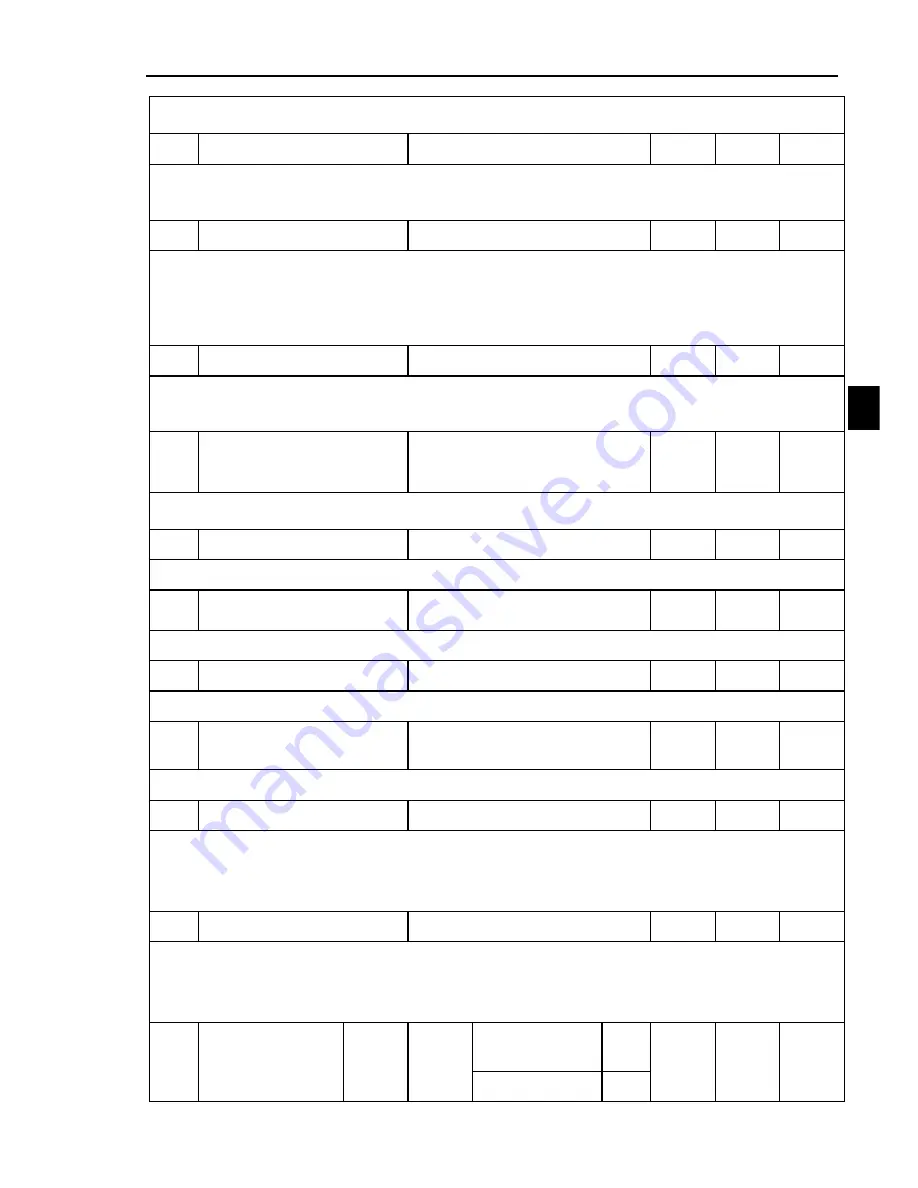
It defines low-speed loop switching frequency, the parameter and switching frequency at
high-speed optimize Speed-loop PID parameter.
C05
Speed loop high speed Ti
0.01~100.00
s
0.50
Y
It defines integration time of High-speed section of the speed loop.Range is
0.01~100.00s.integration time too large and unresponsive, external interference control variation
becomes weak ; integration time is small the reaction speed, oscillation occurs when it is too small
C06
Speed loop high speed Td
0.000~1.000
s
0.000
Y
It defines the differential time of the speed-loop high speed segment and the range is
0.000~1.000s.
If the time is great enough, the surge which is caused by P action when difference occurring
can attenuate quickly. But too great, the surge will happen contrary. When the time is little, the
attenuation function is little too.
C07
Speed loop high speed P
0~150
%
75
Y
It defines the proportion gain of speed loop high-speed section, range from 0~1000%. Gain
is large,response speed, but too large gain will occur vibration; if the gain is small, the reaction
lag.
C08
Speed Loop And High-
speed Switching
Frequency
C04~Max frequency
Hz
30.00
Y
It defines Integral time of speed loop high speed , the parameter and switching frequency at
low -speed optimize the speed-loop PID parameter.
C09
Low-speed slip gain
0~200
%
100
Y
Low-speed segment slip compensation gain
。
C10
Low speed slip switching
frequency
0~C12
Hz
5.00
Y
Low speed segment slip compensation switching frequency
C11
High speed slip gain
0~200
%
100
Y
High speed segment slip compensation gain
C12
High speed slip switching
frequency
C10~Max frequency
Hz
30.00
Y
High speed segment slip compensation switching frequency
C13
Upper froward torque
0.0~300.0
%
250.0
Y
The parameter is a ratio
,
setting value is 100%. Responding to motor rated output torque.
Set forward torque mode through C15.
In speed control mode, it‟s upper forward torque.
In torque control mode, it‟s forward torque setting value.
C14
Upper reverse torque
0.0~300.0
%
250.0
Y
The parameter is a ratio
,
setting value is 100%.
Set reverse torque mode through C16.
In speed control mode, it‟s upper reverse torque.
In torque control mode, it‟s reverse torque setting value
C15
Forward torque
setting mode
1 bit
Setting
mode
Set by keyboard
or RS485
0
-
0000
Y
AI1 external
1