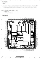
CDJ-800MK2
99
5
6
7
8
5
6
7
8
C
D
F
A
B
E
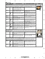
Player (2/4)
Sites
Waveforms
Points to be checked
Causes & Measures to be taken
Remarks
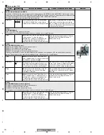
Loading-in attempts are repeated although no CD is loaded.
(On the DATA-FL display, the indications "NO-DISC" and "EJECT" are alternately displayed.)
A CD cannot be loaded.
A failure in the detection system of the slot-in mechanism SV Assy is most likely the cause.
The detection switch detects a trigger signal for operation start or stop of the loading motor.
The present symptom may be caused by the disability of detection of a trigger signal for operation start.
SLMB Assy
z
Visually check if the loading detection switch
(S1902) is kept pressed by the switch lever
(white) as the lever overrides the switch.
Disengage the switch lever from the loading
detection switch (S1902). If the detection switch
is not closely seated on the board, soldering
touchup is needed.
MAIN Assy
MAIN Assy
,
x
Check the SW signal at the LPS2 and LPS1
Test Lands at the time of CD loading, referring to
the waveform photo.
Does the SW signal change from L to H?
Especially pay attention to a change at LPS2.
Repeated loading-in attempts may be caused by
short-circuiting of the line to ground. Disabled CD
loading may be caused by a solder fracture at
the loading detection switch (S1902), soldered
portion lifted off the board of the surface mount
part on the line, or loose connection of the FFC
cables.
MAIN Assy
MAIN Assy
c
By observing the waveform at the PWMLO
Test Land, check that the duty at PWMLO
changes, as indicated in the waveform photo:
• During stop: Duty 50 %
• During loading-in: Duty 0 %
• During loading-out:
Duty changes from 100 %, 25 %, then to 75 %.
MAIN Assy
v
Check the voltage at the MPU (IC301), FPGA
(IC302), IC105 (TC7W04), and the driver IC
(IC102).
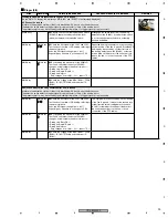
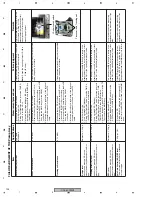
No ejection. Abnormal noise generated after a CD is loaded
A failure in the detection system of the slot-in mechanism SV Assy is most likely the cause.
The detection switch detects a trigger signal for operation start or stop of the loading motor.
The present symptom may be caused by the disability of detection of a trigger signal for operation stop.
MAIN Assy
MAIN Assy
,
z
Check the SW signal at the LPS1 and LPS2
Test Lands at the time of CD loading, referring to
the waveform photo.
Does the SW signal change from L to H?
Especially pay attention to a change at LPS2.
This symptom may be caused by short-circuiting
of the line to ground. It may also be caused by a
solder fracture at the loading detection switch
(S1901), soldered portion lifted off the board of
the surface mount part on the line, or loose
connection of the FFC cables.
MAIN Assy
MAIN Assy
x
By observing the waveform at the PWMLO
Test Land, check that the duty at PWMLO
changes, as indicated in the waveform photo:
• During stop: Duty 50 %
• During loading-in: Duty 0 %
• During loading-out:
Duty changes from 100 %, 25 %, then to 75 %.
MAIN Assy
c
Check the voltage at the MPU (IC301), FPGA
(IC302), IC105 (TC7W04), and the driver IC
(IC102).
3
5
3
5
4
4
Summary of Contents for CDJ-800MK2
Page 27: ...CDJ 800MK2 27 5 6 7 8 5 6 7 8 C D F A B E MODE MODE 3 3 A 27 24 26 19 36 ...
Page 29: ...CDJ 800MK2 29 5 6 7 8 5 6 7 8 C D F A B E Data PANEL DATA Digital A 2 3 3 3 A 3 3 A 23 ...
Page 130: ...CDJ 800MK2 130 1 2 3 4 1 2 3 4 C D F A B E Pin Function ...
Page 135: ...CDJ 800MK2 135 5 6 7 8 5 6 7 8 C D F A B E Pin Function ...
Page 139: ...CDJ 800MK2 139 5 6 7 8 5 6 7 8 C D F A B E Pin Function ...
Page 143: ...CDJ 800MK2 143 5 6 7 8 5 6 7 8 C D F A B E ...
Page 153: ...CDJ 800 7 5 6 7 8 5 6 7 8 C D F A B E ...

