CDJ-800MK2
100
1
2
3
4
1
2
3
4
C
D
F
A
B
E
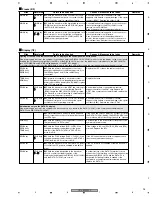
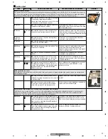
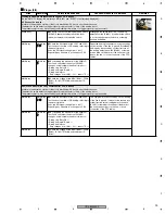
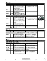
Player (3/4)
Sites
Waveforms
Points to be checked
Causes & Measures to be taken
Remarks
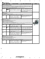
The error rate measured in Test Operation mode of Service mode is high.
z
To which the cause is attributed, disc or
player, must be judged first.
Visually check the disc for stains on the
recording surface.
If the disc is clearly stained, replace it with a
clean CD.
x
Using the disc that produced a high error rate,
measure an error rate at addresses in a different
area.
If the error rate at addresses in a different area is
not high, the CD is defective. Replace it with a
high-quality CD.
If the error rates at addresses in different areas
on the whole disc are high, proceed to Step
3
.
Pickup Assy
c
Check if shavings or dirt are attached to the
pickup lens.
Clean the lens.
Player
v
Check if the TM Assy (servo mechanism) is
securely attached.
Player
b
Check if the loading mechanism SV Assy is
securely attached.
Pickup Assy
n
Check if any foreign object is on the spindle
table.
Remove the foreign object.
Pickup Assy
m
Check if any foreign object is attached to the
magnet section of the Pickup Assy.
Remove the foreign object.
Player
MAIN Assy
, , ,
,
Check the S-curve, TE, RFO, and AGCRF
levels in Service mode.
See "Failure judgment of the Pickup Assy" for
details.
The LD is not turned on after entering Test Operation mode of Service mode.
RLYB Assy
z
Visually check if the LD short-circuit switch
(S1101) remains closed.
Set the LD short-circuit switch to OPEN.
MAIN Assy
x
Check that Pins 41 and 42 on the Servo DSP
(IC101) are open or short-circuited.
Player
c
Check if the FFC cable that connects the
Pickup and the RLYB Assys is securely
connected to the Pickup Assy, if the conductor
side is defective, and if there is any cable
breakage. Also check for loose connection of
connectors.
If the symptom is ameliorated by replacement of
the FFC cable, the defective cable is the cause.
MAIN Assy
v
Check if the R101 to R105 or Q105 are
missing.
MAIN Assy
b
Check if the FFC cable that connects the
RLYB and MAIN Assys is firmly connected to
CN101.
The pickup lens does not move up or down after entering Test Operation mode of Service mode.
Player
z
Check if the FFC cable that connects the TM
and the RLYB Assy is securely connected to the
Pickup Assy, if the conductor side is defective, or
if there is any cable breakage. Also check for
loose connection of connectors.
If the symptom is ameliorated by replacement of
the FFC cable, the defective cable is the cause.
Pickup Assy
x
Check if the resistance of the focus coil is too
large or if the focus coil is broken, using Service
mode.
See "Failure judgment of the Pickup Assy" for
details.
MAIN Assy
c
Check if the 7 V power is supplied to Pin 32 of
IC102.
MAIN Assy
MAIN Assy
v
Check if the signal output from the FOO
terminal on the MAIN Assy oscillates centered
around 1.65 V.
LD short-circuit switch
1
2
8
11
9
Summary of Contents for CDJ-800MK2
Page 27: ...CDJ 800MK2 27 5 6 7 8 5 6 7 8 C D F A B E MODE MODE 3 3 A 27 24 26 19 36 ...
Page 29: ...CDJ 800MK2 29 5 6 7 8 5 6 7 8 C D F A B E Data PANEL DATA Digital A 2 3 3 3 A 3 3 A 23 ...
Page 130: ...CDJ 800MK2 130 1 2 3 4 1 2 3 4 C D F A B E Pin Function ...
Page 135: ...CDJ 800MK2 135 5 6 7 8 5 6 7 8 C D F A B E Pin Function ...
Page 139: ...CDJ 800MK2 139 5 6 7 8 5 6 7 8 C D F A B E Pin Function ...
Page 143: ...CDJ 800MK2 143 5 6 7 8 5 6 7 8 C D F A B E ...
Page 153: ...CDJ 800 7 5 6 7 8 5 6 7 8 C D F A B E ...


