CDJ-800MK2
98
1
2
3
4
1
2
3
4
C
D
F
A
B
E
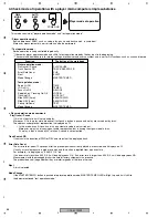
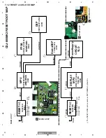
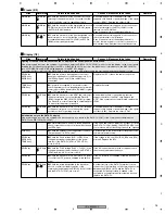
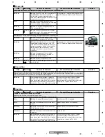
Digital output
Player (1/4)
Sites
Waveforms
Points to be checked
Causes & Measures to be taken
Remarks
No digital output
First, check if neither analog nor digital signals are output. If neither is output, the AUDIO DSP (IC701) is in failure. During CD
playback, first check the digital output terminal (JA802) then the previous stages. Be sure to carefully check for solder fractures at
the digital output terminal.
JACK Assy
z
Check the waveform of the digital audio signal
at the digital output terminal (JA802).
JACK Assy
x
Check if the analog audio signal is output from
the analog output terminal (JA801).
If neither digital nor analog audio signal is output,
the AUDIO DSP (IC701) does not function
properly. Proceed to Step
v
.
MAIN Assy
MAIN Assy
c
Check the waveform at the point designated.
No signal suggests lifted soldered portion of the
AUDIO DSP (Pin 69 of IC701) or chip fracture on
the line. If there is a signal output, poor cable
connection, loose connection of the connectors,
or solder fracture of the phono plug is suspected.
MAIN Assy
MAIN Assy
v
Check the waveform at the DSP16M Test
Land, to confirm that the 16 MHz clock signal is
supplied from the MPU (IC301) via the FPGA
(IC302).
MAIN Assy
MAIN Assy
, , ,
, ,
b
Check the waveform at the point designated,
to confirm that the configuration procedures
between the MPU (IC301) and the AUDIO DSP
(IC701) are properly performed.
An unstable waveform suggests loose
connection of the output terminal or chip fracture.
Sites
Waveforms
Points to be checked
Causes & Measures to be taken
Remarks
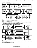
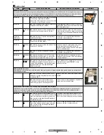
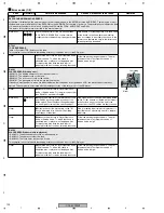
No disc playback.
A disc is ejected immediately after it is loaded. (without an error code)
RLYB Assy
z
Visually check if the LD short-circuit switch
(S1101) remains closed.
Set the LD short-circuit switch to OPEN.
Player
x
Check if the slot-in mechanism SV Assy is
securely hooked to the player unit.
Firmly secure the Assy with the four hooks.
Pickup Assy
c
Visually check if solder is short-circuited at the
LD short-circuit Land on the Pickup Assy.
Unit
v
Check if the FFC cables between the pickup
and the RLYB Assy and the RLYB and MAIN
Assys are improperly connected, if the conductor
side is defective, and if there is poor contact,
such as cable disconnection. Also check for
loose connection of connectors.
If the symptom is ameliorated by replacement of
the FFC cable, the defective cable is the cause.
MAIN Assy
b
Check the voltage of each section on the
MAIN Assy.
MAIN Assy
n
Replace the MAIN Assy.
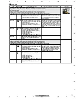
A disc cannot be loaded.
Unit
z
Check if the FFC cables between the pickup
and the RLYB Assy and the RLYB and MAIN
Assys are improperly connected, if the conductor
side is defective, and if there is poor contact,
such as cable disconnection. Also check for
loose connection of connectors.
If the symptom is ameliorated by replacement of
the FFC cable, the defective cable is the cause.
MAIN Assy
x
Check the voltage of each section on the
MAIN Assy.
MAIN Assy
c
Replace the MAIN Assy.
LD short-circuit switch
LD short-circuit land
70
29
21 26 31
32 34 35
Summary of Contents for CDJ-800MK2
Page 27: ...CDJ 800MK2 27 5 6 7 8 5 6 7 8 C D F A B E MODE MODE 3 3 A 27 24 26 19 36 ...
Page 29: ...CDJ 800MK2 29 5 6 7 8 5 6 7 8 C D F A B E Data PANEL DATA Digital A 2 3 3 3 A 3 3 A 23 ...
Page 130: ...CDJ 800MK2 130 1 2 3 4 1 2 3 4 C D F A B E Pin Function ...
Page 135: ...CDJ 800MK2 135 5 6 7 8 5 6 7 8 C D F A B E Pin Function ...
Page 139: ...CDJ 800MK2 139 5 6 7 8 5 6 7 8 C D F A B E Pin Function ...
Page 143: ...CDJ 800MK2 143 5 6 7 8 5 6 7 8 C D F A B E ...
Page 153: ...CDJ 800 7 5 6 7 8 5 6 7 8 C D F A B E ...


