CDJ-800
63
5
6
7
8
5
6
7
8
C
D
F
A
B
E
1
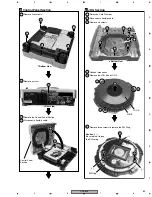
Remove five screws.
2
Remove a screw.
3
Remove the Control Panel Section.
4
Disconnect a flexible cable.
Control Panel Section
3
1
Release a Cord Clamper.
2
Disconnect a flexible cable.
3
Remove six screws.
4
Unhook three hooks.
5
Remove the JOG B and JOG A.
6
Remove three screws to remove the SW Ring.
Caution
(
∗
)
:
Be careful not to lose
the SW spring.
JOG Section
4
JOG A
Control Panel
Section
1
1
1
3
3
3
4
4
4
5
3
6
6
6
3
3
1
1
Bottom View
Bottom View
Rear View
JOG B
SW Ring
(
∗
)
(
∗
)
(
∗
)
2
3
CN56
4
CN500
2
1
Summary of Contents for CDJ-800MK2
Page 27: ...CDJ 800MK2 27 5 6 7 8 5 6 7 8 C D F A B E MODE MODE 3 3 A 27 24 26 19 36 ...
Page 29: ...CDJ 800MK2 29 5 6 7 8 5 6 7 8 C D F A B E Data PANEL DATA Digital A 2 3 3 3 A 3 3 A 23 ...
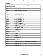
Page 130: ...CDJ 800MK2 130 1 2 3 4 1 2 3 4 C D F A B E Pin Function ...
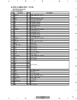
Page 135: ...CDJ 800MK2 135 5 6 7 8 5 6 7 8 C D F A B E Pin Function ...
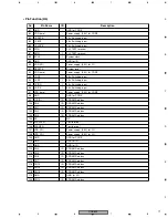
Page 139: ...CDJ 800MK2 139 5 6 7 8 5 6 7 8 C D F A B E Pin Function ...
Page 143: ...CDJ 800MK2 143 5 6 7 8 5 6 7 8 C D F A B E ...
Page 153: ...CDJ 800 7 5 6 7 8 5 6 7 8 C D F A B E ...

