2 How to get started (CameraLink
®
)
The sensor has no cover glass, therefore dust on the sensor surface may resemble
to clusters or extended regions of dead pixel.
To
choose
a
lens,
see
the
Lens
Finder
in
the
’Support’
area
at
www.photonfocus.com.
5.
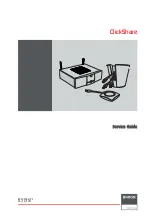
Connect the camera to the frame grabber with a suitable CameraLink
®
cable (see Fig. 2.2).
CameraLink
®
cables can be purchased from Photonfocus directly (www.photonfocus.com).
Please note that Photonfocus provides appropriate solutions for your advanced vision
applications.
Figure 2.2: Camera with frame grabber, power supply and cable.
Do not connect or disconnect the CameraLink
®
cable while camera power is on!
For more information about CameraLink
®
see Section 4.13.
6.
Connect a suitable power supply to the provided 7-pole power plug. For the connector
assembly see Fig. A.1. The pinout of the connector is shown in Appendix A.
Check the correct supply voltage and polarity! Do not exceed the maximum
operating voltage of +12V DC (
±
10%).
7.
Connect the power supply to the camera (see Fig. 2.2).
✎
The status LED on the rear of the camera will light red for a short moment, and
then flash green. For more information see Section 5.1.4.
10
Summary of Contents for CameraLink MV1-D1312 series
Page 1: ...User Manual MV1 D1312 I CameraLink Series CMOS Area Scan Camera MAN041 09 2010 V2 5...
Page 2: ......
Page 4: ...2...
Page 8: ...CONTENTS 6...
Page 14: ...2 How to get started CameraLink 12...
Page 24: ...3 Product Specification 22...
Page 72: ...4 Functionality Figure 4 56 Unsharp Mask Examples 70...
Page 110: ...8 Mechanical and Optical Considerations 108...
Page 112: ...9 Warranty 110...
Page 114: ...10 References 112...
Page 118: ...A Pinouts 116...