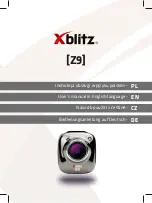
³ 2 0 8
P i x e l
³
2 0 8 P i x e l
³ 2 0 8
P i x e l
+ m o d u l o 3 2 P i x e l
³ 2 0 8
P i x e l + m o d u l o 3 2 P i x e l
a )
b )
Figure 4.19: Possible configuration of the region of interest with MV1-D1312(I)-80 CMOS camera
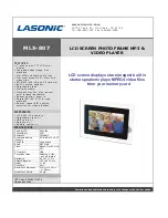
³
2 7 2 p i x e l
³
2 7 2 p i x e l
³
2 7 2 p i x e l
+ m o d u l o 3 2 p i x e l
³
2 7 2 p i x e l + m o d u l o 3 2 p i x e l
a )
b )
Figure 4.20: Possible configuration of the region of interest with MV1-D1312(I)-160 CMOS camera
Any region of interest may NOT be placed outside of the center of the sensor. Examples shown
in Fig. 4.22 illustrate configurations of the ROI that are NOT allowed.
4.3 Reduction of Image Size
35
Summary of Contents for CameraLink MV1-D1312 series
Page 1: ...User Manual MV1 D1312 I CameraLink Series CMOS Area Scan Camera MAN041 09 2010 V2 5...
Page 2: ......
Page 4: ...2...
Page 8: ...CONTENTS 6...
Page 14: ...2 How to get started CameraLink 12...
Page 24: ...3 Product Specification 22...
Page 72: ...4 Functionality Figure 4 56 Unsharp Mask Examples 70...
Page 110: ...8 Mechanical and Optical Considerations 108...
Page 112: ...9 Warranty 110...
Page 114: ...10 References 112...
Page 118: ...A Pinouts 116...