3 Product Specification
3.2
Feature Overview
Characteristics
MV1-D1312(I) Series
Interfaces
CameraLink
®
base configuration
Camera Control
PFRemote (Windows GUI) or programming library
Configuration Interface
CLSERIAL (9’600 baud or 57’600 baud, user selectable)
Trigger Modes
Interface Trigger / External opto isolated trigger input
Image pre-processing
Shading Correction (Offset and Gain)
3x3 Convolver included on camera
2 look-up tables (12-to-8 bit) on user-defined image region (Region-LUT)
Features
Greyscale resolution 12 bit / 10 bit / 8 bit (MV1-D1312-240: 8 bit only)
Region of Interest (ROI)
Up to 512 regions of interest (MROI)
Test pattern (LFSR and grey level ramp)
Image information and camera settings inside the image (status line)
Crosshairs overlay on the image
High blooming resistance
Opto isolated trigger input and opto isolated strobe output
Table 3.1: Feature overview (see Chapter 4 for more information)
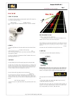
Figure 3.1: MV1-D1312(I) CMOS camera series with C-mount lens.
.
14
Summary of Contents for CameraLink MV1-D1312 series
Page 1: ...User Manual MV1 D1312 I CameraLink Series CMOS Area Scan Camera MAN041 09 2010 V2 5...
Page 2: ......
Page 4: ...2...
Page 8: ...CONTENTS 6...
Page 14: ...2 How to get started CameraLink 12...
Page 24: ...3 Product Specification 22...
Page 72: ...4 Functionality Figure 4 56 Unsharp Mask Examples 70...
Page 110: ...8 Mechanical and Optical Considerations 108...
Page 112: ...9 Warranty 110...
Page 114: ...10 References 112...
Page 118: ...A Pinouts 116...