3 Product Specification
800
1000
1200
30%
40%
50%
60%
V
/
J
/
m
²
]
m
E
ff
ic
ie
n
c
y
QE Responsivity
0
200
400
600
0%
10%
20%
30%
200
300
400
500
600
700
800
900
1000
1100
R
e
s
p
o
n
s
iv
it
y
[
V
Q
u
a
n
tu
m
Wavelength [nm]
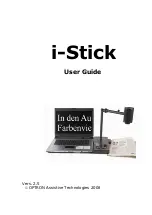
Figure 3.3: Spectral response of the A1312I image sensor (NIR enhanced) in the MV1-D1312I camera series
3.4
Frame Grabber relevant Configuration
The parameters and settings, which are essential to configure the frame grabber are shown in
the following table. The timing diagrams of the camera are given in Section 4.1.2.
MV1-D1312(I)-40
MV1-D1312(I)-80
MV1-D1312(I)-160
Pixel Clock per Tap
40 MHz
40 MHz
80 MHz
Number of Taps
1
2
2
Greyscale resolution
12 bit / 10 bit / 8 bit
12 bit / 10 bit / 8 bit
12 bit / 10 bit / 8 bit
Line pause
36 clock cycles
18 clock cycles
18 clock cycles
CC1
EXSYNC
EXSYNC
EXSYNC
CC2
not used
not used
not used
CC3
not used
not used
not used
CC4
not used
not used
not used
Table 3.7: Summary of parameters needed for frame grabber configuration
CameraLink
®
port and bit assignments are compliant with the CameraLink
®
standard (see [CL]).
Table 3.9 summarizes the tap configurations for the MV1-D1312(I)-40 cameras. Table 3.10
shows the tap configurations for the MV1-D1312(I)-80 and MV1-D1312(I)-160 cameras. Table
3.11 shows the tap configurations for the MV1-D1312(I)-240 and cameras.
18
Summary of Contents for CameraLink MV1-D1312 series
Page 1: ...User Manual MV1 D1312 I CameraLink Series CMOS Area Scan Camera MAN041 09 2010 V2 5...
Page 2: ......
Page 4: ...2...
Page 8: ...CONTENTS 6...
Page 14: ...2 How to get started CameraLink 12...
Page 24: ...3 Product Specification 22...
Page 72: ...4 Functionality Figure 4 56 Unsharp Mask Examples 70...
Page 110: ...8 Mechanical and Optical Considerations 108...
Page 112: ...9 Warranty 110...
Page 114: ...10 References 112...
Page 118: ...A Pinouts 116...