


Connection examples of safe inputs
108928_en_02
PHOENIX CONTACT
51 / 84
Device diagnostics and behavior of the Smart Element in the event of an error
Table 7
-
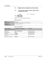
3
1-channel: supply through OSSD
Error type
Detec
-
tion
Diagnos
-
tics
Loss of
SF
1
Comment
Error in the sensor
(depending on the sensor)
Please take into consideration errors that can occur in the
sensor.
Error in the wiring
Interrupt
Input
(cable interrupt between sensor
and input)
Yes if
state is
“1”
None
No
The error is detected as a change in state from “1” to “0”.
An unexpected change from “0” to “1” is possible.
Make sure that this change in state cannot restart the sys
-
tem unintentionally.
GND terminal
(cable interrupt between sensor
and GND)
Yes if
state is
“1”
None
No
The sensor must detect the error.
The sensor must ensure that the safe state is entered in the
event of an error.
The error is detected as a change in state from “1” to “0”.
An unexpected change from “0” to “1” is possible.
Make sure that this change in state cannot restart the sys
-
tem unintentionally.
Cross-circuit
Prevent cross-circuits to achieve the specified safety integrity level.
Input to input
No
None
Yes
The error cannot be detected and results in the loss of the
safety function, as the safety switch is bypassed.
Input to clock output
No
None
Yes
The error cannot be detected and results in the loss of the
safety function, as the safety switch is bypassed.
Input to external 24 V
No
None
Yes
The error cannot be detected and results in the loss of the
safety function, as the safety switch is bypassed.
Clock output to external 24 V
No
None
No
The error cannot be detected as clocking is disabled.
Short circuit
Input to ground
Yes if
state is
“1”
None
No
The error is only detected as a change in state from “1” to
“0” in state “1” of the input. An unexpected change from “0”
to “1” is possible.
Make sure that this change in state cannot restart the sys
-
tem unintentionally.
Clock output to ground
Yes
Short
circuit
No
The error is detected as a short circuit of the clock output.
The affected clock output is disabled.
External 24 V to ground
Yes
None
No
The error is only detected as a change in state from “1” to
“0” in state “1” of the input. An unexpected change from “0”
to “1” is possible.
Make sure that this change in state cannot restart the sys
-
tem unintentionally.
1
SF = safety function