


Parameterization
108928_en_02
PHOENIX CONTACT
41 / 84
6.2.3
Two-channel non-equivalent assignment
In 2-channel operation of the inputs, the channels are assigned permanently.
– IN0_CH1 to IN0_CH2
– IN1_CH1 to IN1_CH2
– IN2_CH1 to IN2_CH2
– IN3_CH1 to IN3_CH2
The following applies for 2-channel non-equivalent assignment: the state only changes from
“0” to “1” when input INx_CH1 changes state from “0” to “1” and input INx_CH2 changes
state from “1” to “0”.
The following applies if symmetry monitoring is enabled: if the state at both inputs does not
change within the parameterized time, a diagnostic message is generated.
See
“Symmetry and start inhibit” on page 42
.
The active state is present when the state of the signal at channel 1 is equal to “1”, and at
channel 2 is equal to “0”.
State evaluation
The Smart Element evaluates the states of the inputs and transmits the result to the control
-
ler.
The following values are transmitted in the process data image of the safe inputs:
– “1” if a “1” signal is present at channel 1 of the input and a “0” signal is present at
channel 2 of the input
and
no error has been detected and the conditions are met for a
.
– “0” in any other cases
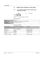
Example of correct and incorrect signal change
Figure 6
-
3
Correct signal change
Figure 6
-
4
Error during signal change
When switching on the sensor again please note the following: a delayed change in state
at one of the two inputs can result in delayed transmission of state “1” in the process data
image of the inputs.
1
0
1
0
1
0
IN0_C 1
H
IN0_C 2
H
IN0 (C 1/C 2)
H
H
1
0
1
0
1
0
IN0_C 1
H
IN0_C 2
H
IN0 (C 1/C 2)
H
H