
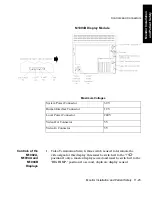
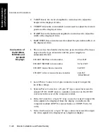


Controls and Connectors
11-30 Monitor Installation and Patient Safety
M
onitor
Ins
ta
lla
ti
on
a
nd Pa
ti
e
n
t Sa
fe
ty
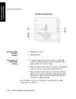
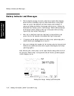
loudspeaker is not covered and can be heard. The most suitable
location for the External Alarm Device is in close proximity to the
ITE display.
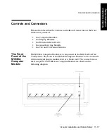
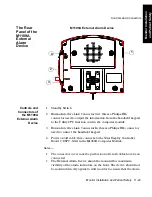
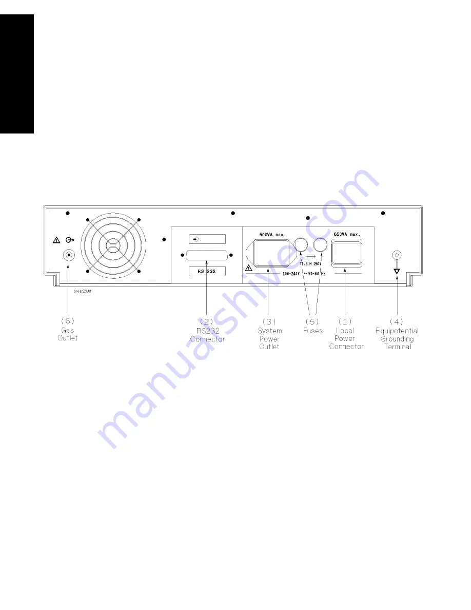
The Rear
Panel of the
M1026A
Anesthetic
Gas Module
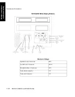
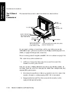
The connections on the rear panel of the Anesthetic Gas Module are
shown in the following diagram:
The rear of the Anesthetic Gas Module has the following connections:
1. Local Power connector; a 3-pin connector is used to input the local
line voltage.
2. RS232 Connector (RS232 Interface); a 25-pin “D” type connector is
used for connection to the ACMS.
Note—
Do not apply a voltage greater than
±
12V to the RS232
connections.
3. System Power Outlet (restricted use); this can be used to output
power to the Philips M1165A/66A/75A/76A ACMS.
MONITOR
Summary of Contents for M1165
Page 12: ...Responsibility of the Manufacturer xii ...
Page 62: ...Using an ITE Display 1 40 The CMS and V24 and V26 Patient Monitors ...
Page 74: ...Attaching the Patient 2 12 Getting Started Getting Started ...
Page 172: ...Alarm Setup 5 16 Alarm Functions Alarm Functions ...
Page 228: ...Loading Paper 6 56 Recording Functions ...
Page 236: ...Admitting a Patient 7 8 Admit Discharge End Case Admit Discharge End Case OR Mode ...
Page 238: ...Admitting a Patient 7 10 Admit Discharge End Case Admit Discharge End Case endcase tif ...
Page 274: ...Drug Calculator 8 36 Trends and Calculations Trends and Calculations ...
Page 299: ...Data Transfer Module Data Transfer 10 3 Data Transfer M1235A CTS DTM CMS CMS V24 V26 ...
Page 388: ...Performance Assurance Checks 13 22 Maintenance Maintenance ...