background image

Performing and Reviewing Calculations

8-20     Trends and Calculations  

Tr

e

nds

 a

nd 

Calcula

tion

s


Performing and Reviewing Calculations

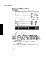
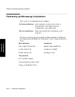
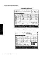
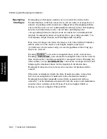
There are two calculation functions available:

The three calculation groups available are Hemodynamics, Ventilation, 
and Oxygenation. Examples of values which can be calculated are given 
below.

Perform calculations 

where parameter values can be entered 
automatically or manually to perform 
calculations in a specified group 

Review calculations 

where previously made calculations can be 
examined 

Hemodynamics

Ventilation

Left Cardiac Work (LCW) 

Minute Volume (MINVOL) 

Cardiac Index (CI) 

Compliance (COMP) 

Stroke Volume (SV)

Dead Space (Vd)

Oxygenation

Percent Shunt (Qs/Qt) 

Venous Oxygen Content (CvO

2

Oxygen Consumption (VO

2

)

Summary of Contents for M1165

Page 1: ...PHI Philips M1165 66 67 75 76 77A CMS Patient Monitoring System and Philips M1205A V24 and V26 Patient Monitor User s Reference Manual Volume 1 System Information Part Number M1046 9220L Printed 02 2003 ...

Page 2: ...Philips Medical Systems makes no warranty of any kind with regard to this material including but not limited to the implied warranties or merchantability and fitness for a particular purpose Philips Medical Systems shall not be liable for errors contained herein or for incidental or consequential damages in connection with the furnishing performance or use of this material 2003 Philips Medizin Sys...

Page 3: ...D The M1167 77A Systems comply with UL2601 1 CSA 22 2 No 601 1 M90 IEC 601 1 EN 60601 1 and EN 60601 1 2 and carries Marking to Council Directive 93 42 EEC European Medical Device Directive MDD The M1205A Systems comply with UL2601 IEC 601 1 CSA C22 2 no 601 1 EN60601 1 and EN60601 1 2 and carries Marking to Council Directive 93 42 EEC European Medical Device Directive MDD 0366 0366 0123 ...

Page 4: ...s If the coupling is through the power cord plugging the patient monitor into a different circuit may help Reduce the sensitivity of the system In all of the EMC testing the patient monitor was adjusted to maximum sensitivity For the ECG amplifier the gain was four times what is normally required By reducing the gain of the system receiving the EMI the interference can often be eliminated Add exte...

Page 5: ...e devices The Philips M1165 66 67 75 76 77A CMS Patient Monitoring System and the Philips M1205A V24 and V26 Patient Monitors are not therapeutic devices Environment The Philips M1165 66 67 75 76 77A CMS Patient Monitoring System and the Philips M1205A V24 and V26 Patient Monitors are intended to be used in a clinical environment by trained healthcare professionals They are not intended for home u...

Page 6: ... tissue of the patient Signals are obtained from accessory electrode transducer and sensor devices Frequency of Use The Philips M1165 66 67 75 76 77A CMS Patient Monitoring System and the Philips M1205A V24 and V26 Patient Monitors are indicated for use when prescribed by a clinician Physiological Purpose The Philips M1165 66 67 75 76 77A CMS Patient Monitoring System and the Philips M1205A V24 an...

Page 7: ...Indications for Use vii Prescription Versus Over the Counter The Philips M1165 66 67 75 76 77A CMS Patient Monitoring System and the Philips M1205A V24 and V26 Patient Monitors are prescription devices ...

Page 8: ... use this equipment in the presence of flammable anesthetics Alarms Do not rely exclusively on the audible alarm system for patient monitoring Adjustment of alarm volume to a low level or off during patient monitoring may result in patient jeopardy Remember that the most reliable method of patient monitoring combines close personal surveillance with correct operation of monitoring equipment This e...

Page 9: ... be sure the SDN interface cable is properly secured at both ends when connecting to the Philips monitoring network SDN Do not connect a second rack by a cable when using a module rack docked to the back of the V24CT or V26CT Using a second rack connected by a cable may disrupt module communication Caution A caution calls attention to a condition or possible situation that could cause injury to th...

Page 10: ...rable A list of Philips Sales and Support Offices is provided at the end of this manual Notice to the User Although there may be products in your area that look similar to the Philips M1165 66 67 75 76 77A CMS Patient Monitoring System and the Philips M1205A V24 and V26 Patient Monitors their functionality may not be the same This User s Reference Manual is intended to be used with the Philips M11...

Page 11: ...structions for use To ensure optimum usage we recommend that Philips parts and accessories are used in conjunction with the Philips M1165 66 67 75 76 77A CMS Patient Monitoring System the Philips M1026A Anesthetic Gas Module and the Philips M1205A V24 and V26 Patient Monitors wherever available If non Philips parts are used Philips Medical Systems is not liable for any damage that these parts may ...

Page 12: ...Responsibility of the Manufacturer xii ...

Page 13: ...on Module Section 15 Noninvasive Blood Pressure Module Section 16 SpO2 PLETH Module Section 17 Temperature Module Section 18 CO2 Module and Sidestream Module Section 19 FIO2 Module Section CMS only 20 Pressure Module Section 21 Cardiac Output Module Section 22 VueLink Module Section Volume 3 contains chapters 23 to 29 and appendices A to E see the table of contents of Volume 3 for more details 23 ...

Page 14: ...ng System 1 2 V24 and V26 Patient Monitor 1 7 Control Panel 1 8 The Handheld Keypad 1 10 External Alarm Device 1 11 Hardkey Functions 1 12 V26CT V24CT Power Supply 1 14 Battery Power Supply 1 14 Parameter Modules 1 16 Symbols to Indicate Key Functions 1 17 Operating Levels 1 20 Main Screen 1 21 Selection Window 1 23 Task Window 1 24 Getting into the Operating Levels 1 25 Touch or Mouse Trackball O...

Page 15: ...6 only 2 2 Setting up the Parameter Modules 2 5 Attaching the Patient 2 6 Adjusting Screen Contrast 2 7 Starting Monitoring 2 8 Screen Messages 2 8 Reserving a Channel 2 9 Power Failure 2 10 Patient Information Center 2 10 Monitor Standby 2 10 Setting up your Monitor 3 1 Changing Display Screens 3 2 Selecting a Screen 3 3 Procedure 3 3 Freezing Waves CMS only 3 4 What you Can Configure 3 5 Changes...

Page 16: ...dure 3 30 Trace Mode 3 31 Procedure 3 31 Configuring a Second Independent Display CMS only 3 32 Other Functions You Can Configure 3 33 Adjusting the Volume Control 3 35 Procedure 3 35 Adjusting the Date and Time 3 37 Procedure 3 37 Selecting Waves for Central Recorders 3 39 Configuring Module Bedside and Central Recordings 3 40 Other Patients Controls 3 41 The Status Log Function 3 42 The Monitor ...

Page 17: ...nfiguring the Other Patients Controls 4 7 Using Philips Patient Care System with an Arrhythmia Computer 4 8 Extended Overview CMS only 4 15 To View an Extended Other Patients Bed 4 16 Alert Notification 4 17 Alarm Functions 5 1 Alarm Display 5 2 Alarm Functions on the Control Panel 5 2 Suspending Alarms 5 3 Silencing and Resetting Alarms 5 4 Alarm Priorities 5 8 Individual Parameter Alarms 5 10 Wh...

Page 18: ...initions 6 20 Configuring Preset Recording Modes 6 21 Making Preset Recordings 6 22 Making Non Preset Recordings 6 22 Making Calibrated ECG Recordings 6 23 If the Recorder is Busy 6 23 Realtime Vital Signs Blood Recordings 6 25 Definitions 6 25 Making a Single Vital Signs Blood Recording 6 27 Making Timed Sequences of Vital Signs Blood Recordings 6 27 Trended Vital Signs Recordings 6 29 Header Inf...

Page 19: ...ller on the Four Channel M1117A Recorder 6 55 Admit Discharge End Case 7 1 Admitting a Patient 7 2 Changing Patient Information 7 5 Discharging a Patient Ending a Case 7 9 Trends and Calculations 8 1 Introduction to Trends Calculations 8 2 Viewing Patient Data 8 3 Trending Priority 8 5 Viewing Blood Measurements 8 5 Viewing Vital Signs 8 9 Selecting Parameters for Graph Trends 8 12 Viewing Graph T...

Page 20: ...ndicate Key Functions 10 5 What is Transferred 10 5 Types of Transfer 10 7 To Module 10 7 To Monitor 10 10 Transferring Blood Analysis Data 10 11 Combining Data 10 14 Time Conversion 10 14 Database Conversion 10 14 Vital Signs Blood Review and Graphs 10 17 Time Stamp 10 17 Reports 10 18 Troubleshooting 10 19 Performance Specifications 10 20 Data Transfer Module 10 20 Monitor Installation and Patie...

Page 21: ...ng Information 11 37 Battery Information V24CT and V26CT only 12 1 AC and DC Battery Operation 12 2 Operating Instructions 12 3 Battery Indicator and Messages 12 6 External Battery Charger 12 8 Battery Care and Maintenance 12 9 Storage 12 9 Care and Handling 12 10 Accessories and Ordering Information 12 11 Maintenance 13 1 General cleaning of the System 13 2 General Disinfecting of the System 13 4...

Page 22: ... Self Test 13 17 Performing the tcpO2 tcpCO2 Module Self Test 13 18 Performing the CO2 Module Self Test 13 19 Performing the Temperature Module Self Test 13 19 Performing the Blood Analysis Module Self Test 13 20 Performing the Recorder Module Self Test 13 20 Performing the Data Management Database Self Test 13 20 Tests for VueLink Module and Anesthetic Gas Module 13 21 ...

Page 23: ... Patient Monitoring Systems and V24 and V26 Patient Monitors It includes the following sections Introduction 1 2 Parameter Modules 1 16 V26CT V24CT Power Supply 1 14 Operating Levels 1 20 Touch or Mouse Trackball Operation 1 27 The CMS Computer Modules 1 33 The V24 and V26 Parameter Module Rack 1 35 Operating Rules to Remember 1 36 ...

Page 24: ...onitors The respective sections are marked throughout the manual with either CMS only or V24 and V26 only The following system types are available CMS Patient Monitoring System The CMS Patient Monitoring System is available as a choice of three system types Each system consists of three individual parts a display module a computer module and parameter modules 1 M1167 77A Color Flatscreen Display a...

Page 25: ... CMS and V24 and V26 Patient Monitors 1 3 The CMS and V24 and V26 Patient Monitors M1167 77A System Display Module M1095A 10 4 Flatscreen Display Computer Module M1046B Computer Module Parameter Modules Satellite Rack ...

Page 26: ... offers the M1167 77A H05 and H07 XGA Touchscreen display configuration b A 15 flat touchscreen display is also available separately under the order number M1097A A02 A 17 CRT touchscreen display is also available separately under the order number M1098A Computer Module M1046B Computer Module Parameter Modules Satellite Rack Parameter Modules External Alarm Device XGA Display Computer Module ...

Page 27: ...es Note In this manual the system will be referred to as the CMS the ACMS and the NCMS Display Module M1094A B 92A 14 CRT Display Computer Module M1046A Computer Module Parameter Modules Integral and or Satellite Rack Full Title Abbreviation The Philips CMS Patient Monitoring System CMS The Philips CMS Patient Monitoring System for Anesthesia Care ACMS The Philips CMS Patient Monitoring System for...

Page 28: ...d V24 and V26 Patient Monitors Display Modules Below are labeled diagrams of the display modules provided by Philips Medical Systems The control panel is described in more detail in the following sections M1095A Flatscreen Display Module M1092A M1094B CRT Display Module ...

Page 29: ...ular model monitor you have purchased either a A monochrome display with control panel supporting the V24 or b A color flat panel display with control panel supporting the V24C the V24CT the V26C and the V26CT 2 The Rack with Parameter Modules The V24 V24C and V26C are powered by connection to an AC power supply The V24CT and V26CT can be powered by rechargeable batteries or by connection to an AC...

Page 30: ...The hardkeys have only one function defined by the label on the key The hardkeys are labeled in blue Each one of these keys gets you into a level where adjustments and changes can be made or performs an immediate action The keys are labeled according to their function for example key allows you to start a recording of a waveform Note If you are using the M1167 77A system with the External Alarm De...

Page 31: ...llow alarm condition exists CMS Control Panel V24 and V26 Patient Monitor Control Panel Note Earlier versions of the V24 feature a key instead of the key Procedures Monitor Setup Realtime Record Delayed Record Trends Module Alarms Main Screen Silence Reset Suspend Confirm Other Patients Setup Calcs Alarm Lamps Alarms Suspended Lamp Trends Trends Calcs ...

Page 32: ...mbers punctuation marks and arithmetic symbols Note The handheld keypad is the main means of operating the M1167 77A System with External Alarm Device Do not remove the keypad from systems with touch or mouse trackball operation as it is still required to perform certain tasks Softkeys and Hardkeys The softkeys and hardkeys on the keypad are in the same relative position and operate in the same ma...

Page 33: ...l is pressed again The softkeys and hardkeys work as normal External Alarm Device CMS only Since the External Alarm Device is used only with commercially available ITE displays that do not have a control panel it contains all the alarm lamps the Alarms Suspended Lamp and the loudspeaker It does not contain any hardkeys or softkeys and therefore can only be used in conjunction with the Handheld Key...

Page 34: ... screen press to enable you to suspend or switch on alarms set and review alarm limits enter Monitor Standby or set the alarm volume press to enable you to view data from other beds in your group press to enable you to pre select certain system characteristics press to enable you to set up and perform procedures such as Cardiac Output Wedge Pressure CMS only ST analysis Drug Calculations admit and...

Page 35: ...rrow keys allow you to move between areas on operating screens to enable you to change or adjust settings perform procedures or make changes to the screen display Key This key functions only when it is illuminated A prompt message press CONFIRM appears on the screen when you need to use it CMS only Press to view airway gases or ventilator waves and numerics Confirm Airway Gases Ventilation ...

Page 36: ...ce The power cord must be inspected periodically for cracks or exposed metal parts Replace immediately if there are any cracks exposed metal parts or any other signs of wear and tear Battery Power Supply The V24CT and V26CT can be powered by 1 or 2 sealed 12 Volt lead acid batteries with capacity The rate of battery discharge is dependent on temperature and power load The power load is a function ...

Page 37: ...te Charging time is 4 hours to 90 of full capacity if the monitor is off 16 hours to 90 of full capacity if the monitor is on Note When AC is connected and the monitor is on the Battery Charge LEDs may take some time to cycle to the appropriate charge indication and may underreport battery capacity during this setting period Use the fuel gauge rather than the Battery Charge LEDs during this period...

Page 38: ...nt of the module and get into the parameter setup window or task window a light appears above the key The connector socket on the front of each module is the same color as the corresponding connector plug on the transducer or patient cable Note If a T is present on the front of a module certain parameter settings may be transferred with that module when it is moved from one rack to another This be...

Page 39: ... press the key marked with the corresponding start symbol The design change also means that you will now find the module s product number for example M1032A on the rear of the module s housing not on the front Although the new modules do not show the letter T on the housing all modules retain their capability to transfer parameter settings from one monitor to another Symbol Name Function Which Mod...

Page 40: ...g in depends on the type of rack and the model of monitor you have ordered Rack Type Mounting Comments CMS Patient Monitoring System Integral Rack This is fitted to the front of the M1046A computer module Cannot be used with the M1167 77A CMS Patient Monitoring System 8 slot rack Satellite Rack You can have one or more satellite racks attached to an I V pole bedside or wall Can be used with all CM...

Page 41: ...le are plugged in a message detailing where the extra module is appears in the system message field Currently ignored module in rack position R P where The message Unrecognized module in rack position R P is displayed if an unknown module is plugged into the rack Note Since the V24 and V26 Patient Monitors only support one module rack R will always be 1 R is the number of the rack e g 1 integral r...

Page 42: ...24 and V26 Patient Monitors Operating Levels There are three types of screens which you will see on the display module The three types of screen and the interconnections between them are shown below Standard Display 1st Level 2nd Level Control Panel Selection Window Task Window ...

Page 43: ...You can configure the number and position of the waveforms on the display screen The numerics are aligned with the corresponding waves The numeric information is updated every two seconds With the color model the numeric appears in the same color that you have assigned to the corresponding waveform The hardkey always returns you directly to the Main Screen Note The Main Screen of the V24 and V26 P...

Page 44: ...nt Monitors HR 70 135 72 94 ST1 ST2 ABP PAP 23 SpO 2 2 ETCO IMCO 19 47 2 AWRR 0 37 0 3 0 2 PULSE NBP 115 65 81 ICU Adult 10 JAN 95 20 05 II F HR 1mV ABP 120 0 PLETH SpO 2 SQI CO2 40 0 34 16 97 70 20 CHANNEL 1 LAYOUT 1 NON OVERLAP CHANNEL 2 CHANNEL 3 CHANNEL 4 NUMERICS Alarm Vol 165 QRS Vol 150 ...

Page 45: ...keys on the control panel When you get into the Selection Window the bottom line is always active This is indicated by a bar below the keys and the yellow labeling The selection can be changed within the Selection Window one line at a time For information on how to change the selection see page 1 25 There is also an arrow symbol in the Window that moves along the selected line when the cursor keys...

Page 46: ... operating level which allows you to make changes or adjustments to the parameters and screen displays or to perform procedures Each parameter or procedure has a series of Task Windows There are two ways to get into the second operating level via the Selection Window or for parameters by pressing the Setup key on the parameter module ...

Page 47: ... softkey corresponding to the parameter or function you require or This gets you into the Task Window For example to get into the Noninvasive Blood Pressure NBP Task Window 1 Press the hardkey 2 If it is not already active select the line containing NBP by pressing again 3 Press the softkey to get into the Noninvasive Blood Pressure Task Window Task Window There are two ways to get into a paramete...

Page 48: ...e an adjustment to a setting 1 To move to the next Task Window press the softkey for the function you require for example This gets you into the Filter Mon Diag Task Window where you can make any necessary adjustments 2 To make an adjustment change the selection by pressing the softkey for that window again until the adjustment or change you want is active or use the arrow keys if they are illumin...

Page 49: ...s touchscreen displays mouse or trackball operation of the monitor Since these displays do not contain a control panel there are slight differences in operating the system The following sections contain the instructions specific to touch mouse or trackball operation V24C and V26C monitors with option T01 allow touch operation in addition to the standard operation Mouse and Trackball operation is n...

Page 50: ...r of the display These buttons are touch responsive and can be used alternatively to the hardkeys of the control panel or the handheld keypad Note Do not remove the keypad from systems with touch or mouse trackball operation as it is still required to perform certain tasks Control Panel Task Window The Control Panel Task Window contains most of the hardkeys found on the control panel of non touch ...

Page 51: ...ck a white appears and the area is surrounded by a white frame In addition an audible click is issued The white frame disappears automatically when the object is released If an object or area of the screen that is not touch responsive is touched a white x appears in the selected area Note When using a mouse trackball the white and x signs appear wherever the mouse trackball pointer is currently lo...

Page 52: ... Selections within Task Windows can be directly selected by touch or mouse click without the Select Item softkey or the arrow keys Arrow Keys Depending on the application buttons are provided to perform the task of the arrow keys Confirm Button A confirm button is displayed in the lower right corner of the task window every time a confirm is required Application Windows Split Screen oxyCRG and CSA...

Page 53: ...ted with the Touch Board softkey e g from the Patient Admit Task Window The Touchboard Task Window contains a subtitle which references the Task Window from which the Touchboard was accessed Data entry can be performed for one item at a time Press to save edited data Press or to navigate through the editable items of the Task Window the Touchboard was accessed from Press to return to the Task Wind...

Page 54: ...panel button in the lower right corner of the main screen for at least four seconds A padlock icon over the control panel button indicates when touch and mouse trackball operation is disabled To re enable touch and mouse trackball operation press and hold or click and hold the padlock icon for at least two seconds The control panel button will reappear Note If a task window is opened or the monito...

Page 55: ...ayed on the screen as waveforms and numerical readouts M1046A Computer Module The M1046A Computer Module is for use with the Philips M1165 66A and the Philips M1175 76A CMS Patient Monitoring System The parameter module rack can be attached to the computer module or a blank panel can be fitted to the computer module if you want to use a satellite parameter module rack Maximum Voltages ECG Output a...

Page 56: ... computer module is used during cardioversion to provide an ECG waveform for synchronizing a defibrillator It is also used to receive a marker pulse from the defibrillator for indicating the defibrillator discharge in the ECG waveform on the monitor display If you are using a Philips defibrillator without a built in recorder the marker pulse from the defibrillator is returned to the monitor If the...

Page 57: ...e display module In addition the V24CT and V26CT allow you to dock a 6 slot rack directly to the mainframe Warning Warning Do not connect a second rack by a cable when using the V24CT or V26CT with a 6 wide rack docked to the mainframe Docking a second rack by a cable may disrupt module communication The signals from the parameters being monitored are transmitted to the internal computer where the...

Page 58: ...election Window press a hardkey What is labeled in yellow and appears pushed in is active Softkeys function only in the Selection and Task Windows with the exception of the Alarm Volume Control and the QRS Tone Volume Control on the V24 and V26 Patient Monitors The parameter module Setup key gets you directly into a Task Window The arrow keys and key are illuminated when available for use Main Scr...

Page 59: ... XGA Flatscreen Display Useful Screen 5 unless otherwise noted 158 mm x 211 mm 6 2 x 8 3 Pixel Size 0 33 mm x 0 33 mm Storage Time at 25 mm sec 5 5 seconds Trace Speeds 6 25 12 5 25 50 mm sec 10 Useful Screen 5 unless otherwise noted 180 mm x 225 mm 7 1 x 8 9 Pixel Size 0 22 mm x 0 35 mm Storage Time at 25 mm sec 6 seconds Trace Speeds 6 25 12 5 25 50 mm sec 10 Useful Screen 5 unless otherwise not...

Page 60: ... the EN60601 1 A1 A2 IEC601 1 A1 A2 or it must conform to the requirements of an IEC XXX electrical safety standard and fulfill specific requirements according to the EN60601 1 1 A1 IEC601 1 1 A1 to provide the same level of safety as EN60601 1 IEC601 1 The display must be constructed or protected so that spillage of liquids does not wet parts of the display which may cause a safety hazard IEC601 ...

Page 61: ...o be done Perfor mance Require ments Philips cannot assure compliance with the ANSI AAMI EC 13 Standard for Cardiac Monitors Heart rate Meters and Alarms when using ITE displays Compliance with the ECG aspect ration and 25 mm s 10 sweep speed specifications can only be assured when using the Philips Displays M1092A M1094B and M1095A In addition the following display specifications are recommended ...

Page 62: ...Using an ITE Display 1 40 The CMS and V24 and V26 Patient Monitors ...

Page 63: ...ve been introduced to the monitor you are probably ready to start using it This chapter will help you get started It contains the following sections Setting up the Monitor V24 and V26 only 2 2 Setting up the Parameter Modules 2 5 Attaching the Patient 2 6 ...

Page 64: ...26 only 1 Attach the parameter module rack to the display module by a cable to the connector on the left side of the display module If you are using the V24CT or V26CT you can attach the 6 slot rack to the back of the mainframe display without the need for a cable The two components will snap or dock together ...

Page 65: ...click into place when properly inserted Caution Philips Medical Systems recommends you fully charge the batteries before using the V24CT or V26CT for the first time Plug the monitor into an AC power supply line power for an initial charging cycle When the monitor is plugged in and the power is off it takes approximately four hours for the batteries to reach a charge of 90 capacity and nine hours f...

Page 66: ...nitoring network SDN cable when the product is powered on is not supported Error codes and Philips monitoring network SDN interface lock up may occur Power cycling the product will recover the product No permanent damage will result To prevent unintentional disruption in monitoring be sure the SDN interface cable is properly secured at both ends when connecting to the Philips monitoring network SD...

Page 67: ... the module clicks into place To remove a module press the lever upwards and pull the module out See diagram below 3 Check that you have the correct patient cables and transducers plugged into the modules The module connectors are color coded to the patient cables and transducers for easy identification Your monitor may have Parameter Settings Transfer set ON To understand the effect this has when...

Page 68: ... patient 2 Connect the electrodes probes and transducers to the appropriate modules After less than 10 or 20 seconds you should see a display on the screen similar to the one under Main Screen in Section 1 The number of waveforms depends on the waveforms you have selected to have displayed and also on the model of your system The numerics are aligned with the corresponding waveform ...

Page 69: ...MS The brightness and contrast of the screen display can be adjusted by means of the two dials underneath the hardkeys Follow this procedure to achieve the optimum screen display 1 Turn the brightness and contrast controls to their maximum settings 2 Slowly turn the brightness and contrast controls down to the lowest acceptable position where the display can still be seen clearly The most acceptab...

Page 70: ...o the screen display see the section Configuring the System If you want to make changes to the parameter settings see the individual parameter sections Switch the system alarms ON by pressing the key so that the Alarm Suspend lamp goes out The patient is now being monitored Screen Messages Two types of messages appear at the top of the display screen Prompt messages these instruct the user to perf...

Page 71: ... a Channel A parameter module may be turned OFF but left in the rack The empty channel where the waveform should be still appears on the Main Screen There is no waveform waveform label or numeric Another wave may use its screen channel temporarily but will be discarded as soon as the assigned wave is reactivated This ensures that particular waveforms can always be allocated to the same place on th...

Page 72: ...ead for ECG channels 1 and 2 the wave is not displayed in channel 2 of the Patient Information Center Monitor Standby If you want to stop patient monitoring but keep all settings and Patient Data Management information you can switch the monitor into Monitor Standby 1 Press or 2 Press All waves and numerics disappear from the display and all monitoring is suspended The word Standby appears in big ...

Page 73: ...r You will hear the overview prompt tone two double beeps but the Alarm Bed Task Window will not be displayed To resume monitoring simply press one of the keys except on the control panel on the front of the display or on the handheld keypad CMS only The changes and adjustments that you made to the settings before going into Monitor Standby are retained Patient Data Management information collecte...

Page 74: ...Attaching the Patient 2 12 Getting Started Getting Started ...

Page 75: ...e Speeds 3 15 Displaying Split Screen Trends 3 22 oxyCRG Display 3 25 CSA Display CMS only 3 28 Configuring a Second Independent Display CMS only 3 32 Adjusting the Volume Control 3 35 Adjusting the Date and Time 3 37 Selecting Waves for Central Recorders 3 39 Configuring Module Bedside and Central Recordings 3 40 Other Patients Controls 3 41 The Status Log Function 3 42 The Monitor Revision Funct...

Page 76: ...ens A softkey corresponding to each screen is available in the Change Screen Task Window CMS or the Monitor Setup Task Window V24 and V26 The display screen which is active is identified by an inactive softkey for that screen You can change to one of the other screens at any time by pressing one of the other softkeys You can reconfigure only the screen which is currently active Once a display scre...

Page 77: ... is not the currently active screen you must select the required screen for example Screen A Screen B Screen C screen D or Screen E Procedure 1 Press the hardkey CMS or V24 and V26 2 Press the softkey corresponding to the screen you want to change The Main Display appears for the selected screen Change Screen Monitor Setup ...

Page 78: ...can freeze any wave movement on the screen via the keys Press or any other key except or to restart the waves You can also freeze the waves on your 2nd and 3rd independent display To restart the waves on an independent display press Change Screen Freeze Waves Start Waves Suspend Silence Reset Start Waves ...

Page 79: ...revert back to their default settings factory defaults or user defaults if the system is switched off for longer than 60 seconds The settings for the date and time are stored by the system when it is switched off Note If necessary these default settings can also be changed This is done in a special configuration mode either by your biomedical engineering department or the Philips service engineer ...

Page 80: ...tion To make changes to the settings you need to get into the Monitor Setup Selection Window The key sequence to get into the Task Windows is shown above the screen figures in this guide The softkeys are indicated in the text like this The hardkeys are indicated in the text like this Display Monitor Setup ...

Page 81: ...label The description includes Assigning Waves to Screen Channels Selecting a Screen Selecting Screen Labels for Realtime Display Screens Selecting the Number of Waves Selecting the Wave Overlap Configuration Selecting Realtime Wave Speeds Numerics On Off Selecting an Application Window Wave Replace Mode Trace Mode A description is then given for changing a completely separate display screen ...

Page 82: ...Waves to Screen Channels You can assign realtime waves to positions on the screen This defines where the waves appear on the Main Screen Notes You can also return to the Display Setup Task Window from the Realtime Speeds Task Window by pressing the softkey Display Setup Monitor Setup Display1 Setup ...

Page 83: ...h wave position you want to change 4 Press to return to the Main Screen screen Note If one of the assigned waves is not available parameter switched off or unplugged then another wave will use its channel until the assigned wave is reactivated provided Wave Replace Mode is enabled The channel will only remain blank if It is assigned to ECG or Blank Another wave is available but numerics aligned to...

Page 84: ...1 Press until Screen Choice is selected on the screen 2 Press to select a screen A E The selected screen choice and its screen label will appear at the top of the Task Window The other items on the screen will change depending on the configuration of the different screens 3 Press to return to the Main Screen Monitor Setup Display1 Setup Select Item Select Item Change Content Main Screen ...

Page 85: ...ens A screen label may be selected for a realtime display screen There are eleven choices Procedure 1 Press until Screen Label is selected on the screen 2 Press to select the key label that you require The choices are a Neuro b Cardvasc c SwanGanz d Standard e Ventilat f Perfusn g Surgeon Monitor Setup Display1 Setup Select Item Select Item Change Content ...

Page 86: ...eturn to the Main Screen screen User Defined Screen Labels In addition to the pre defined screen labels you can define your own labels for each screen A E To define a screen label 1 Select User Def in the Display Setup Task Window 2 Press 3 Enter new label using either the handheld keypad the touchboard CMS only or the arrow keys V24 and V26 4 Press 5 The user defined labels will also appear in th...

Page 87: ...he screen within the capabilities of the model you have ordered Procedure 1 Press until NumbrOfWaves is selected on the screen 2 Press to choose 4 6 or 8 waves to be displayed depending on your model 3 Press to return to the Selection Window or to return to the main screen Monitor Setup Display1 Setup Select Item Select Item Change Content Monitor Setup Main Screen ...

Page 88: ...w a larger wave amplitude and you can compare waveforms of various parameters i e pressure waves Procedure 1 Press until Overlap is selected on the screen 2 Press to choose one of the available numbers dependent on model The boxes in the middle of the screen indicate which waves are overlapping 3 Press to return to the Selection Window or to return to the Main Screen Monitor Setup Display1 Setup S...

Page 89: ...ct the speed for the waveforms from the following 50 mm sec 25 mm sec 12 5 mm sec 6 25 mm sec Procedure To select different speeds for the waveforms 1 Press the softkey repeatedly to select a parameter to which you want to assign a different speed 2 Press repeatedly to select the speed you require 3 Repeat steps 1 and 2 for each parameter speed you want to change Monitor Setup Display1 Setup Realt...

Page 90: ...n to the Realtime Waves Task Window press to return to the Selection window or to return to the Main Screen Note The speed of the Resp or CO2 waves and of the AG waves must always be set individually You cannot alter their speeds by pressing If waves overlap all the waves travel at the speed of the wave in the first overlapping channel If the overlap is then changed to non overlapping waves each w...

Page 91: ...meters results in more of the remaining numerics being displayed in large digits 1 Press the softkey to highlight the required parameter numeric To view parameters which are not displayed press the softkey 2 Press the softkey to set the selected numeric display on or off 3 Repeat Steps 1 and 2 for each numeric that requires resetting 4 Press the softkey to switch ALL numerics on or off at the same...

Page 92: ...n of numerics on the screen and also controls the size of some numerics Numeric Positions Numerics are positioned on the screen in the following order 1 Parameters with waveforms such as Pressure are positioned first The numerics are aligned with the corresponding waveform 2 Numerics which are part of a contiguous block i e CO2 AGM ST BIS HR PULSE are positioned next 3 Parameters without waveforms...

Page 93: ... one temperature is being monitored the additional temperatures are shown continuously in rotation in the position of the third temperature numeric Invasive pressures are multi numeric parameters because each pressure has numerics for systolic diastolic and mean pressures They are decreased in size Pressure 1 P1 numerics preferably stay big Additional Information The ST1 ST2 and ST3 values are sho...

Page 94: ...Split Screen oxyCRG CSA They are described in more detail in the following sections Procedure 1 Press until ApplicWindow is selected on the screen 2 Press to choose Split OxyCRG CSA or None no application window to be displayed 3 Press to return to the selection window or to return to the Main Screen Monitor Setup Display1 Setup Select Item Select Item Change Content Monitor Setup Main Screen ...

Page 95: ...neously Special Implications for Touch or Mouse Operation If Split Screen is active and a split trend is selected the Graph Trends Window opens up displaying the selected parameter in combination with the adjacent parameters If the oxyCRG display is active and is selected the Neonatal Event Review Window opens up If Neonatal Event Review is not available the Graph Trends Task Window opens up If th...

Page 96: ... trend values are updated every minute The trend value itself is calculated as the average of all the values sampled with the previous minute With Split Screen trending you can Display the preceding 30 minutes of trend data for all vital signs next to their waves Obtain a clear indication if a patient s vital signs tend towards exceeding the alarm limits Note Split Screen Trends are not available ...

Page 97: ...le is displayed for the alarm range Instead the default range scales are displayed with low intensity on the left side of the trend display to distinguish them from alarm limits Trend data is only displayed for those vital signs that are positioned in the left column of the numeric display Viewing Trend Data for Invasive Blood Pressure Three trend values are displayed for invasive pressure systoli...

Page 98: ... alarm limits apply is displayed with a thicker line than the other trends Viewing Trend Data for Non invasive Blood Pressure Because the NBP is not a continuously measured parameter a special symbol is used to display the trend values as shown in the diagram below Display of Trend Data for Non invasive Blood Pressure Example ...

Page 99: ...d on the Main Screen Beat to beat heart rate trend An oxygen parameter trend Compressed respiration wave Approximately the last six minutes of information is displayed for each parameter Main Screen Display with oxyCRG The oxyCRG display can help you to make early detections of respiratory regulation problems in neonates by comparing trend patterns or finding interrelationships among the three par...

Page 100: ...channel disappears from the display The softkey has no effect on the oxyCRG section of the Main Screen because the display speed is very low The beat to beat heart rate btbHR in the oxyCRG display will vary from the heart rate HR numeric on the Main Screen since the HR numeric is an averaged value If the monitor is switched off for less than 60 seconds oxyCRG data is retained However when the powe...

Page 101: ...ens after the power is restored If you are using a touchscreen selecting the oxyCRG display either via touch or mouse click will open up the Neonatal Event Review Task Window or the Graph Trends Window if Neonatal Event Review is not available You can find information about oxyCRG recording in Chapter 6 ...

Page 102: ...sses a large amount of data into a compact easy to read trend and consists of 30 complete spectral lines The bottom half of the Main Screen area is covered with the CSAs The number of realtime waves that you can display simultaneously with CSA is related to the maximum number of realtime waves that your system is capable of displaying Details are provided in the following table ...

Page 103: ...the parameters are still being monitored and the parameter alarms are still active If CSA covers part of an overlap channel the entire overlap channel disappears from the display If you are using a touchscreen selecting the CSA display via touch or mouse click will open up the EEG Setup Task Window Standard Display CSA Display 4 realtime waves CSA 2 realtime wave 6 realtime waves CSA 3 realtime wa...

Page 104: ...temporarily with another wave Procedure 1 Press until Wave Replace is selected on the screen 2 Press to enable or disable Wave Replace With Wave Replace enabled assigned but currently unused channels will be filled with another wave 3 Press to return to the selection window or to return to the Main Screen Monitor Setup Display1 Setup Select Item Select Item Change Content Monitor Setup Main Screen...

Page 105: ...aces Procedure 1 Press until Trace Mode is selected on the screen 2 Press to choose fixed or moving traces 3 Press to return to the selection window or to return to the Main Screen Note Moving Trace is not recommended for flatscreen displays Monitor Setup Display1 Setup Select Item Select Item Change Content Monitor Setup Main Screen ...

Page 106: ...ations blinking messages or or alarm controls or outputs alarm sounds or lamps You can change the screen to have the same display as the main display or you can have a different configuration There are again five separate display screens the default names are Screen A Screen B Screen C Screen D and Screen E To get into the Task Windows press in the Monitor Setup Selection Window The procedures are...

Page 107: ...r recording on the monitor 1 Press the softkey to highlight the required parameter To view parameters which are not displayed press the softkey 2 Press the softkey to set the selected parameter on or off Repeat this procedure for each parameter you want to set 3 Press the softkey if you want to preset parameter settings when the module is plugged in WITHOUT the transducer Switch this setup off aga...

Page 108: ...ESP or NBP disconnect the transducer or adapter cable from the module and suspend or silence the alarms If you switch off a parameter you can ONLY enter the parameter s Setup Task Window via the module s hardkey by first pressing When you plug in a parameter module and connect the transducer or adapter cable the parameter is automatically switched on ECG RESP and NBP are automatically switched on ...

Page 109: ...channels to indicate each QRS complex or pulse trigger event picked up Procedure CMS or or 1 Increase or decrease the QRS or alarm tone volume by pressing the corresponding softkeys If there is currently no active alarm or INOP two short alarm tones sound at each press of the alarm tone keys so that you can hear the effect of changing the volume Monitor Setup Volume Control Alarms Volume Volume Co...

Page 110: ...t corner of the display V24 and V26 Patient Monitor If not already in the Main Screen press Increase or decrease the QRS or alarm tone volume by pressing the corresponding softkeys directly under the Alarm Volume and QRS Volume indicators Monitor Setup Main Screen On Off Tone Mod Main Screen HR 70 135 72 94 ST1 ST2 ABP PAP 23 SpO 2 2 ETCO IMCO 19 47 2 AWRR 0 37 0 3 0 2 PULSE NBP 115 65 81 ICU Adul...

Page 111: ...when the system is turned off If your monitoring system is connected to a central station via a Philips monitoring network the date and time on your monitor is automatically taken from the central station Procedure 1 Change the day month year hour and minute by pressing the corresponding softkeys 2 Press after all the adjustments have been made and a message will appear with the date and time sett...

Page 112: ...s to return to the Selection Window or to return to the Main Screen Note If you are using a touchscreen display arrow buttons will appear above and below the date and time fields These can be selected to adjust the date and time instead of pressing the arrow keys Monitor Setup Main Screen ...

Page 113: ...splayed at the central station With a single channel recorder you can record the primary wave or with a dual channel recorder you can record the primary and secondary waves The primary wave defines which wave is the default wave at the central station and at other bedsides in the overview screen When ECG is available it must be selected as the primary wave it cannot be deselected The procedures fo...

Page 114: ...recordings can be produced on module 4 channel bedside or central recorders Note To ensure an optimal realtime recording check that the recording configuration is appropriate for your recorder 3 Monitoring Procedure Recordings on a module bedside or central recorder You can record the curves produced during cardiac output and pulmonary artery wedge pressure measurements 4 Vital Signs Recordings Au...

Page 115: ...Other Patients Controls If your system is connected via the Philips monitoring network to other bedsides you can choose to send alarms receive alarms and assign your bed to a care group The procedures for setting up the networking system are described in Chapter 4 Other Patients ...

Page 116: ...The Status Log Function 3 42 Setting up your Monitor Setting up your Monitor The Status Log Function The softkey is used by service engineers It produces a list of accumulated error codes Status Log ...

Page 117: ...on Setting up your Monitor 3 43 Setting up your Monitor The Monitor Revision Function The softkey is used by service engineers It gives information about the current hardware and software revision of the monitor Monitor Revision ...

Page 118: ...n the user default settings and the factory default settings are the same You can change the patient category within a Configuration Set during normal monitoring However if after delivery of your system you want to change any of the other parameters or universal settings you will need to contact your Philips service engineer or your biomedical engineering department as this procedure has to be don...

Page 119: ... all the parameter settings and patient data management information are kept if you change the patient category without changing Configuration Set Possible exceptions occur because measurement ranges and alarm limit ranges for some parameters are different for each patient category see the following list If active alarm limits are no longer within range after you change patient category the alarm ...

Page 120: ...s the neonatal algorithm if you choose either the Neonatal or Pediatric patient category If you choose the Adult patient category the ECG parameter uses the adult algorithm The following pages describe in detail how the choice of patient category influences monitoring Parameter Patient Category Adult Pedi Neo NBP Adult Pedi Neo ECG Adult Neo Neo HR PULSE Adult Neo Neo RESP Adult Adult Neo Inv Pres...

Page 121: ...ety values If the cuff pressure exceeds these values for more than a given time period the cuff immediately deflates and a severe INOP Alarm is given These values are adapted to normal physiological values NBP Examples Overpressure Overpressure occurs if the cuff maintains a pressure above the safety value for more than two seconds The safety values are Continuous Pressure Continuous Pressure occu...

Page 122: ...st the measurement ranges and safety values for each patient category NBP Measurement Range in mmHg for Differing Patient Categories Measurement Range Patient Category Adult Pedi Neo Systolic 30 to 270 30 to 180 30 to 130 Mean 20 to 255 20 to 160 20 to 120 Diastolic 10 to 245 10 to 150 10 to 100 Cuff Size A to E Any Cuff 1 to 4 A Default Inflation Pressure 165 mmHg 125 mmHg 100 mmHg NBP Safety Val...

Page 123: ...propriate cuff size a cuff that is too large prolongs inflation time 3 Use a repetition time appropriate to the patient ECG The following factors can cause the cardiotach to calculate an incorrect heart rate Morphology of the ECG Weak signal Paced patients Morphology of the ECG Philips offers two different ECG algorithms to allow for differing morphologies Max deflation time 80s 80s 60s Max measur...

Page 124: ...actors A 1 mV calibration bar at the left side of the ECG channel enables you to estimate the quality of the signal Recommendation Use the strongest signal on channel 1 and compare the QRS amplitude with the 1 mV bar the height should be at least half of that size If not change the lead or try a different electrode placement Paced Patients Paced pulse rejection is available for patient categories ...

Page 125: ...ssion is used in all three patient categories for the 10 and 30 scales In the Pediatric and Adult categories the algorithm is also used for the 60 scale SpO2 Default for averaging time is 10 seconds for Adult Pedi and Neo Note Default can be changed in Configuration Mode Adult bpm Pedi Neo bpm Cardiotach Range 15 to 300 15 to 350 HR Alarm Limit Range 15 to 250 15 to 300 Pleth Pressure Pulse Alarm ...

Page 126: ...Setting up your Monitor Setting up your Monitor CO2 Note The Apnea alarm delay time cannot be changed Adult Pedi Neo AWRR High Range 10 to 100 rpm 30 to 150 rpm AWRR Low Range 0 to 95 rpm 0 to 145 rpm Delay before alarm sounds 20 s 20 s ...

Page 127: ...etup This procedure will not modify a Configuration Set but will change completely from one Configuration Set to another Note Changing the Configuration Set causes all the monitor s settings to revert automatically to user default settings All patient data is lost Note If you are using the ACMS you will not have a choice of Unit Type as this is automatically set to OR Note If you do not want to st...

Page 128: ...gs Transfer to OFF Procedure The current Configuration Set for the monitor is highlighted and the universal settings are displayed at the top of the Task Window 1 Press the softkey to select the Configuration Set you require The universal settings for the selected Configuration Set are displayed 2 Press the hardkey to switch to the selected set Wait at least one minute before plugging in or removi...

Page 129: ...vel 1 password allows you to select Monitor or Config mode only Level 2 password allows you to select Monitor or Service mode only Level 3 password allows you to select any of the four operating modes listed below Monitor This is the usual operating mode and fully supports patient monitoring If the system is attached to a patient it must be in this mode Config This mode is for configuring the moni...

Page 130: ...urning to Monitoring Mode To exit Config Demo or Service Mode press This will return you to Monitoring Mode without having to enter a password It is also possible to exit demo mode by powering down and restarting the monitor Monitor Setup Operatng Modes Monitor Setup Resume Monitor ...

Page 131: ...2 Press the softkey Move the highlighting to the mode you require 3 The prompt message Press CONFIRM to switch to selected mode appears Press the hardkey The instrument goes through the boot up sequence and reverts automatically to default settings and the mode of your choice becomes active Note If you have entered either Config Service or Demo Mode successfully it is possible to return to Monitor...

Page 132: ...meter module to the screen The aim of the function is to identify broken lines and cables in the signal processing areas Note While the Test Signals function is active no patient monitoring is supported parameter values are not collected Alarms will occur depending on the test values as part of the monitor s self test procedure They are patient alarms See for individual tests for each module ...

Page 133: ...s of the monitor The message Test Signals active no monitoring appears on the screen After 30 seconds the monitor automatically switches back to Monitoring Mode If you want to go back to Monitoring Mode before 30 seconds have elapsed press then Analog Output CMS only The Analog Output function provides eight channels of Analog Output for connection to recorders and other data collection instrument...

Page 134: ...LT mode 30 rpm in PEDI mode 55 rpm in NEO mode Simulated Resp wave and numeric Pressure Simulated square wave and numerics Systolic 120 mmHg ADULT 60 mmHg PEDI NEO Diastolic 0 mmHg ADULT PEDI NEO SpO2 Pleth SpO2 100 Numeric only Pleth Wave on display Simulated Wave tcpO2 tcpCO2 Numeric only tcpO2 60 mmHg 8 0 kPa tcpCO2 40 mmHg 5 3 kPa CO2 Simulated square wave and numerics ETCO2 40 mmHg 6 0 kPa IM...

Page 135: ...ameter settings This behavior permits fast and easy transport and is called Parameter Settings Transfer Note The settings that are stored in each module are detailed in the relevant module chapters of this guide For Parameter Settings Transfer to work on your monitor it must be set ON in a special Service Mode either by your biomedical engineering department or the Philips service engineer After m...

Page 136: ...changing Configuration Sets or operating modes You can find more information about Parameter Settings Transfer in each of the parameter chapters in particular Chapter 20 Pressure Module Section and Chapter 17 Temperature Module Section If Parameter Settings Transfer for your monitor is set OFF parameter settings are NOT transferred with your modules ...

Page 137: ...ettings are automatically stored when you exit the Task Window Check Patient Category and parameter name settings The patient category stored with the settings in the module is different from that of the monitor Either change the patient category for the monitor or change the parameter settings Parameter name unable to store settings in module The parameter module was removed before the settings c...

Page 138: ... module Wait for the message to disappear before pressing the key for that parameter Pressure label check zero and transducer level A pressure module has been plugged in with the transducer connected Zero and calibration values will be taken from the module If the transducer has not been recently zeroed and calibrated or if you are setting up a new measurement do the zero and calibration procedure...

Page 139: ...4 1 4 Other Patients This chapter describes the Other Patients function It includes the following sections Overview 4 2 Philips Patient Care System 4 3 Using Philips Patient Care System with an Arrhythmia Computer 4 8 ...

Page 140: ...eceive alarms between beds in the groups and view data from other beds in your group If you require information about the automatic alarm Other Patients function see the next section If you have an arrhythmia computer attached to your monitor or a central station equipped with arrhythmia channels refer to the Using Philips Patient Care System with an Arrhythmia Computer on page 4 8 ...

Page 141: ...imary wave If you have ECG turned on it is always selected as the primary wave If it is not turned on you can select a primary wave in the System Waves Task Window under Monitor Setup If EASI 12 Lead ECG is configured ON only 5 waves can be transmitted to the central station The Other Patients Selection Window The softkeys in the Other Patients Selection Window contain the bed labels of the beds c...

Page 142: ...rms you receive alarms from beds in your Other Patients group which are configured to transmit alarms If such a bed in your group goes into alarm it can be A totally new alarm A new alarm situation on a bed which is already in alarm There are two ways your monitor can react If it is in Main Screen it reverts automatically to Other Patients mode and enters the Alarm Bed Task Window If it is in a Se...

Page 143: ... an arrow in front of the bed label The unacknowledged alarms are stacked and the beds are viewed in sequence as the alarms arrived If alarms arrive simultaneously they are viewed with the lowest bed number first Each bed in alarm is automatically displayed for 5 seconds When all the alarm beds have been displayed the last bed stays on the display and the softkeys and become active When you have v...

Page 144: ...em 4 6 Other Patients Other Patients the alarm stack viewed by other monitors in the Other Patients group No arrow next to a bed number means either there are no more new alarms or all the existing alarms have been acknowledged ...

Page 145: ...from and sent to beds in group A G as well as the other beds in the ALL group When a bed is assigned to any group in A G alarms are received from and sent to any bed in the same group and also to beds in the ALL group Note The bed will automatically be assigned to the ALL group if the connection to the Philips monitoring network is interrupted for example if the Philips monitoring network cable at...

Page 146: ... 78720A or the M3150A M3153A the arrhythmia monitoring for your monitor must be turned on or off at the computer display Using the 78560A or M2300 this can be done from the central station or from the monitor itself Arrhythmia monitoring is most easily assigned in SELECT BED at the central station or arrhythmia computer or from the ARRHYTHMIA MENU at the monitor The ARRHYTHMIA MENU enables you to ...

Page 147: ...ent In the Delayed ArrhWave Task Window the delayed ECG arrhythmia waveform displays a beat label with each QRS complex See the following table for information on beat labels If arrhythmia is assigned and an arrhythmia alarm occurs the Arrhythmia Validation Task Window will appear automatically on the status display unless you turn it off under Trends Calcs Beat Label Meaning A Artifact beat N Nor...

Page 148: ...HR limit set or 40 bpm whichever is lower VENT TACHY Either VENT RHYTHM with average heart rate tachy HR limit or RUN VPB s tachy run limit with rate for the run tachy HR limit Tachy run limit is adjustable from 3 to 9 using the Change Limits display Tachy HR limit is adjustable from 80 bpm to 120 bpm using the Change Limits display VENT RHYTHM Dominant rhythm of adjacent V s and HR 120 PAIR VPBs ...

Page 149: ...V SV V VENT TRIGEMINY Dominant rhythm of SV SV V SV SV V MULTIFORM VPBs The occurrence of two different shaped VPBs within last 300 beats repeated in the last 60 beats HR XXX UUU Heart rate UUU where UUU is the adjustable bedside high alarm limit The heart rate of XXX is the highest heart rate measured since the alarm was detected HR XXX LLL HR LLL where LLL is the adjustable bedside low heart rat...

Page 150: ...display PACER NON FUNCT Missed beat without pace pulse in paced patient VPBs XX min More than XX VPBs per minute where XX is adjustable from 1 to 30 using the Change Limit display Alarm Minimum Condition Requiring an Alarm EXTREME TACHY Heart rate Tachy limit RUN VPBs 9 Run of VPB s 9 and heart rate esc limit set for VENT TACHY RUN VPB s 3 9 Run of 3 9 VPB s PACER NOT PACE Missed beat without pace...

Page 151: ...Brady limit xxx NON SUSTAIN VT A run of Vs having a ventricular HR V Tach HR limit but lasting for less than the V Tach Run limit VENT RHYTHM A dominant rhythm of adjacent Vs vent rhythm limit and ventricular HR V Tach HR limit RUN PVCs Run of PVCs greater than 2 PAIR PVCs Two consecutive PVCs between non PVCs PACER NOT CAPT No QRS for 1 75 x the average R R interval with Pace Pulse paced patient ...

Page 152: ... supraventricular beat V ventricular beat VENT TRIGEMINY A dominant rhythm of N N V N N V N supraventricular beat V ventricular beat PVCs xxx MIN PVCs within one minute exceeded the PVCs min limit xxx MULTIFORM PVCs The occurrence of two differently shaped Vs each occurring at least twice within the last 300 beats as well as each occurring at least once within the last 60 beats HR yyy xxx Heart Ra...

Page 153: ...rk either in another care unit or in a care unit larger than 24 beds The Extended Overview Task Window provides display of one wave cascaded into two 4 second segments up to seven parameter numerics including arrhythmia if available and alert status messages Extended Other Patients can be in use at a maximum of eight beds in each Philips monitoring network simultaneously When the maximum use is ex...

Page 154: ...ect a group softkey in the following display labeled to bring up bed labels in another unit or for bed labels in a unit larger than 24 beds 3 Select the bed using if necessary The Extended Overview Task Window will be displayed Note that only beds available on the other Philips monitoring network can be selected Other Patients View CCU other Beds More Beds ...

Page 155: ...ed for each bed in turn Alert notification is not provided between care units The operation of receive send alarm choices and group selections is unchanged for Alert Notification Alarms cannot be reset in Alert Notification To view an Alarming Bed from Alert Notification 1 Select to display waves 2 When done select to return to the Main Screen or to view next bed s Alert Notification if more than ...

Page 156: ...y is inoperational the message SDN comm error inter network gateway failed will be displayed in the message area of the main screen display The Alert Notification display is removed if is pressed on the source bedside monitor or on the central station All star star and hard INOP alerts will generate alert notification Silence Reset Silence ...

Page 157: ...Alarm Functions 5 1 5 Alarm Functions This chapter provides general information on alarm functions and what to do if an alarm occurs It includes the following sections Alarm Display 5 2 Alarm Setup 5 12 ...

Page 158: ...nds If there is no sound please check the volume settings If there is more than one red alarm yellow alarm or INOP message you will see an up arrow next to the message The messages are displayed in rotation every 2 seconds If your patient has more than one alarm you can see a list of all these active alarms in the Alarm Messages Task Window To access this Task Window press or followed by Warning W...

Page 159: ...2 ALARMS SUSPND 2 MIN 3 ALARMS SUSPND 3 MIN 4 ALARMS SUSPENDED ALARMS SUSPENDED 1 2 3 MIN In these modes the alarm capability can be switched off but is automatically switched on after 1 2 or 3 minutes unless you have switched it on manually beforehand with the softkey in the Alarms Selection Window or the hardkey ALARMS SUSPENDED In this mode the alarm capability is switched off permanently and m...

Page 160: ...y The ECG HR alarm capability can only be reactivated by switching the main Alarms on or unassigning Arrhythmia Silencing and Resetting Alarms If an alarm occurs you can silence it by pressing the key This will silence ALL alarms that are occurring at that moment The alarm messages numeric will continue to blink You can configure your system on installation to have all latching or all non latching...

Page 161: ...oes not work for arrhythmia alarms It affects the alarm sound lamp nurse call relay and the recorder but not the alarm messages The alarm reminder and reminder time can be configured as follows If you have acknowledged an alarm by pressing the key and the alarm condition continues then the system will behave according to the following configurations Alarm Reminder Reminder Time Off Not Applicable ...

Page 162: ...meter numeric will blink if an alarm condition occurs and Maintain Visual Alarms is set to Yes in a special Configuration Mode by your biomedical engineering department Note The central stations 78560A M2350A and M2360A can be configured to silence and reset the alarms of the bedside monitors If your system is connected to such a central station you can silence an alarm at the central station The ...

Page 163: ... lamp Alarm message blinking numerics Alarm lamp Alarm message blinking numerics Audible alarm reset has been pressed Alarm situation still present Audible alarm silenced Alarm lamp off Audible alarm reminder every 3 minutes if configured Alarm message blinking numerics Audible alarm silenced Alarm lamp off Audible alarm reminder every 3 minutes if configured Alarm message blinking numerics Audibl...

Page 164: ...thmia computer For both the short and continuous yellow alarm the yellow lamp is lit INOPs displayed in the top left corner of the display screen The INOPs also have priority levels they are as follows Equipment Related INOPs These are caused by setup or hardware faults for example ABP NO TRANSDUCER You will hear an INOP tone When an equipment related INOP can have a direct effect on the patient f...

Page 165: ...y across the screen 1 Press or hardkey 2 Press in the Alarms Selection Window Note When an alarm occurs you should always check the patient s condition first Audible Alarms There are four different tones 3 alarm tones and one INOP tone Alarm tones red yellow continuous yellow short INOP tone Alarms Volume Alarms Alarm Messages ...

Page 166: ... OR In this mode all parameter alarms can be switched off with a single key press This enables you for example to quickly switch all alarms off and individually switch on those parameter alarms really needed depending on your monitoring requirements All parameter alarms can be switched off or on using in the Alarm Limits Task Window Note We recommend not to switch off all parameter alarms at once ...

Page 167: ... act appropriately according to the cause of the alarm Identify which monitor is in alarm Check the patient s condition Identify the cause of the alarm Silence the alarm if necessary When alarm condition is eliminated check that the alarm has reset You will find the alarm messages for the individual parameters in the appropriate parameter sections of the Manual ...

Page 168: ...that if you just want to adjust an alarm limit you do not have to get into the individual parameter setups Getting into the Alarms Selection Window Press the hardkey or The first two softkeys and function in the Selection Window If you select one of these softkeys its function is performed and you are returned to the Standard Display Remember you can also suspend the alarms and switch them back on...

Page 169: ...ned off a appears next to the parameter alarm limits 3 Use and softkeys if you want to adjust the limits 4 If there are more than 10 alarm bars to review press the softkey and the remaining alarm bars appear on the screen 5 Stay in the Task Window if you want to adjust more limits or press to return to the Main Screen Alarms Volume Alarm Limits Select Parametr On Off Alarms Low Limit High Limit Ne...

Page 170: ...he up and down arrow softkeys to fill each triangle to the required amount If there is no current alarm or INOP two short alarm tones will sound each time the alarm tone keys are pressed so that you can hear the effect of changing the volume 4 Press to return to the Main Screen Note The QRS tone can be derived from other sources than ECG such as pressure or pleth See Chapter 14 ECG and ECG Respira...

Page 171: ...switched off Note The delay time to the nurse call relay output is max 1 sec When an alarm has been silenced using the key and the audible 2 or 3 minute alarm reminder is configured to be either On or Re alarm the nurse call relay signals will behave as follows Alarm Reminder Reminder Time Nurse Call Relay Signal Behavior On 2 or 3 mins The nurse call relay signals are repeated for a duration of 6...

Page 172: ...Alarm Setup 5 16 Alarm Functions Alarm Functions ...

Page 173: ...s General Recorder Information 6 2 Types of Recordings 6 7 Delayed Recording 6 8 Alarm Recording 6 12 Procedure Recordings 6 16 Realtime Wave Recordings 6 20 Realtime Vital Signs Blood Recordings 6 25 Trended Vital Signs Recordings 6 29 Neonatal Event Review Recordings 6 33 oxyCRG Recordings 6 36 Additional Information 6 39 Recording Status Messages 6 46 Accessories and Ordering Information 6 48 L...

Page 174: ...order records the waves you select for transmission over the Philips patient care system This document provides configuration information for the Plug In 4 channel and central recorders The controls and indicators on the Plug In and 4 channel are also described For information about the 2 channel bedside and the central recorder controls please refer to the relevant operating guide Recorder Model ...

Page 175: ...s on the Plug In Recorder a Continue light Flashes if the currently printing recording is continuous b RUN CONT key Starts a timed delayed recording and or makes a currently printing recording continuous if possible c STOP key Stops the currently printing recording RUN STOP REC M1116B CONT a b c ...

Page 176: ... paper is out or recorder door is open c TEST key Initiates a self test to check that the recorder is working properly and prints a test strip d Speed selection lights Lights to indicate current speed setting e Speed selection keys Selects another printing speed while the recorder is running f Feed key Advances paper until key is released g Continue light Lights when the currently printing recordi...

Page 177: ...Makes oxyCRG recordings M1116B Runtime and delay time are configured when the monitor is installed You can choose layout and speed except for vital signs recordings With oxyCRG recordings layout cannot be chosen Time annotation is at the beginning of printout 4 Channel Recorder M1117A CMS only Makes delayed recordings of any waveforms you select Runtime and delay time are configured when the monit...

Page 178: ...re waveforms viewed at the central station and other monitors in overview mode See the central recorder operating guide for recording speed runtime and delay time Single channel recorder records only the primary wave If ECG is monitored it must be selected as the primary wave It cannot be deselected Dual channel recorder records the primary and secondary wave if the central station supports 2 chan...

Page 179: ...when the recording is initiated Realtime Vital Signs and Blood Analysis made on a M1116A B Plug In recorder Trended Vital Signs made on a M1116A B Plug In recorder Neonatal Event Review made on a M1116B Plug In recorder OxyCRG recordings can be made only on an M1116B Plug In recorder Note Depending on the configuration of your monitor when you press either the Select Recording Waves window appears...

Page 180: ...cted in the Delayed Alarm Recording Task Window The waves recorded on an alarm strip are also chosen from the list in the Delayed Alarm Recording Task Window If the parameter in alarm is not already selected it will replace the last selected channel Delay Time the maximum time between seeing a waveform on the screen and still being able to record it This is configured when the monitor is installed...

Page 181: ...rs and the ECG gain required for 1 mV to equal 1 centimeter on a strip appear below the layout choices c Press to change recorder speed 2 Select wave for each channel a Press to select channel number b Press to select waveform 3 Press to select the type of recording standard or oxyCRG that will be generated by alarms Monitor Setup Recordng Setup On Off Delayed Alarm On Off Change Recorder Select O...

Page 182: ...above 2 Select the waves in the System Waves Task Window a Press to select the primary wave The key does not function if an ECG wave is available In this case the primary wave is always ECG CH1 b Press to select secondary wave c Press to store the selected wave d Press to return to the standard monitoring display Monitor Setup System Waves On Off Waves Change Primary Change Primary Change Second C...

Page 183: ... Task Window Here the waves pre selected for a delayed recording are identified above the Delayed softkey label Note If a delayed recording is configured so that it is produced on a Plug In recorder or a 4 Channel Bedside Recorder alarm recordings are also produced on this recorder If the specified recorder is inoperable for any reason the alarm recording is re routed to the central recorder Remem...

Page 184: ...ion You can determine the alarm severity on a parameter by parameter basis that will cause an alarm recording to run You can also enable and disable alarm recordings for individual parameters With the exception of oxyCRG alarm recordings alarm recordings run at a speed of 25 mm sec regardless of the speed selected in the Delayed Alarm Recording Task Window OxyCRG alarm recordings run at the pre co...

Page 185: ...recordings Note If delayed alarm recordings are being sent to the central recorder the ECG alarm recording setting is displayed in the Alarm Recording On Off Task Window as RED YELLOW This setting cannot be changed unless you choose a bedside recorder either a Plug In or 4 channel bedside Note The AlarmRec On Off function must be enabled in Configuration Mode Monitor Setup Recordng Setup On Off Al...

Page 186: ...lowing priority Parameter whose alarm status has escalated in the last second and has alarm recording enabled Parameter in red alarm with alarm recording enabled Parameter in yellow alarm with alarm recording enabled Parameter in red alarm with alarm recording disabled if space is available Parameter in yellow alarm with alarm recording disabled if space is available Alarm Recording Examples On th...

Page 187: ...he alarm recording items should be set to the following In the event of a Brady Apnea and or Desat alarm the recorder will document an eight minute oxyCRG recording six minutes preceding the event and two minutes following the event Channel 4 Respiration Channel 1 ECG Channel 2 Pressure 1 Channel 3 Pressure 2 Channel 4 CO2 alarm Channel 1 ECG Channel 2 Pressure 1 Channel 3 P3 alarm Channel 4 CO2 a...

Page 188: ...elect the recorder which will record the curve 1 Press to select the recorder that will produce the recording 2 Press to return to the standard monitoring display Note To generate trended vital signs and neonatal event recordings the recorder selection must be set to PLUG IN in the Procedure Recordings task window Monitor Setup Recordng Setup Procedur Recordng Change Recorder Main Screen ...

Page 189: ...e Measure C O Task Window can be recorded by pressing The recording strip shows the curve and is annotated with the date time cardiac output value computation constant blood and injectate temperatures Note Only the most recent cardiac output curve can be recorded Record a curve before including it in an averaging calculation When is pressed all the curves are deleted and cannot be recorded Procedu...

Page 190: ...ings Recordings of ST waves and their reference waves can be made on the bedside or central recorders They are initiated from the ST Analysis Task Window An ST recording shows the ST beat s from the cursor spot in the upper channel and the corresponding reference beat s in the lower channel with the measurement values net change and measurement points listed in the annotation ST values transferred...

Page 191: ...6 19 Recording Functions 91MIA 25 mm sec Ref 01 DEC 8 30 01 DEC 8 35 Change ST1 II 0 2 II 2 1 2 3 ST2 aVR 0 0 aVR 1 0 1 0 ST3 V 0 0 V 0 5 0 5 Iso 72 ms ST Pt 100 ms Ref Iso 72 ms ST Pt 100 ms 01 DEC 93 8 35 ST Ref 1mV 1 3 4 h x 5 3 8 w ST 1mV ...

Page 192: ...d recordings and Mode C to oxyCRG recordings depending on the monitor s configuration A particular mode might be configured to record a specific procedure performed in a unit Realtime recordings can be produced on Plug In 4 channel bedside and central recorders Remember that realtime recordings are initiated in two Task Windows Preset Recordings and Select Recording Waves depending on the type of ...

Page 193: ...ut of the waves on the recording strip c Press to change the recorder speed 2 Select wave for each channel a Press to select required recorder channel b Press to highlight the wave for selected channel 3 Press to give a name to the mode being configured Modes B and C are configured in the same way Monitor Setup Recordng Setup Mode A Recordng Change Recorder Select Overlap Change Speed Select Chann...

Page 194: ... after the recorder name in the order they were selected Each wave that is selected is also identified below the key label The recording is always continuous running at 25 mm s in non overlapped mode To stop realtime recordings either press or press on the recorder All realtime non configured recordings must be stopped manually Realtime Record Preset Recordng Mode A Mode B Mode C Realtime Record S...

Page 195: ...produced Making Calibrated ECG Recordings If you want your ECG recording to be calibrated you must select the size of the ECG wave depending on your recorder sector size To select the size refer to the Switching between EASI and Standard leads on page 14 22 The calibrated ECG wave recording will be 10mm mV If the Recorder is Busy Realtime If a delayed recording or any recording from another monito...

Page 196: ...ee Note If you are using a monitor connected to a Patient Information Center 78504 and 78508 and you are using an 78572 recorder please observe the following rule Always select a valid waveform Do not select Blank as the waveform to be recorded in the Select Recording Waves Task Window as the recorder will not function It will give the prompt Central recorder not available For the Monitor connecte...

Page 197: ... of vital signs blood analysis at specific timed intervals Recordings can include Just vital signs data Just blood analysis data A combination of vital signs and blood analysis data Vital signs blood recordings are made only at the bedside on the M1116A B plug in recorder this type of recording is not rerouted to a central recorder if the bedside recorder is not available 92MIA 06 JUN 94 11 08 52 ...

Page 198: ... set by the system and cannot be adjusted Note If vitals signs blood recordings are configured on when the monitor is turned off a vital signs recording will be generated within the 30 seconds after the monitor is turned back on If vital signs blood recordings are configured on when the system clock is changed a recording will be generated immediately Subsequent recordings will be generated based ...

Page 199: ...the Vital Signs Blood Recording Task Window under Monitor Setup Recorder Setup You can also determine whether vital signs recordings will be initiated on an NBP measurement a blood analysis measurement at a specific time interval or any combination of the above New configuration choices become effective when you leave the Vital Signs Blood Recording task window Any recordings currently active will...

Page 200: ...cordings 6 28 Recording Functions Recording Functions If you are configured for vital signs blood recordings and you are in Mode B selecting the Vital Signs Blood Recording key produces a recording consistent with NBP configuration ...

Page 201: ...before trended vital signs can be recorded You can access the Procedure Recordings task window by selecting on the control panel and in the Monitor Setup selection window Header Information Each trended recording begins with a header page which contains general information such as date time patient s name medical record number and the bed label 1 Recording code 2 Date and Time 3 Patient s name 4 R...

Page 202: ...t be adjusted The trended parameters are recorded in the same order as those displayed in the Vital Signs task window and the Vital Signs report Please refer to the Trends and Calculations section later in this manual Chapter 8 Volume 1 for further information on the data displayed in the Vital Signs task window and the Vital Signs report Note Blood Analysis parameters are not included in a trende...

Page 203: ...me line 7 Diastolic 2 Data that has been transferred 8 Mean 3 Date 9 Time of measurement 4 Time setting has been altered during time period 10 Questionable value 5 Parameter labels 11 More than one value is available in the time period 6 Systolic 12 Value has been entered manually ...

Page 204: ...corded by selecting the softkey To stop trended vital signs recordings The recording can be stopped at any time by selecting in the Preset Recording task window on the recorder itself or by beginning another procedure recording The time intervals and the time span can be changed by selecting and Trends Calcs Vital Signs Vitals PLUG IN Stop Recordng STOP Zoom In Time Zoom Out Time ...

Page 205: ...port Neonatal Event Review recordings Header Information Each neonatal event recording begins with general information such as the recording date time patient s name medical record number and the bed label Beneath this comes the Event Summary information including the total number of stored events and their respective event categories See the Neonatal Event Review section of this manual Chapter 9 ...

Page 206: ... in a tabular format by selecting the softkey oxyCRG Episode Recordings for Neonatal Events An oxyCRG episode for a selected neonatal event can be recorded on the M1116B Recorder Module from the oxyCRG Episode task window Header Information Each oxyCRG episode recording begins with general information such as the date time patient s name medical record number and the bed label Beneath this is a ta...

Page 207: ...or and 2 minutes past the captured event alternatively 1 minute 3 minutes configurable For manually captured events 4 minutes prior the captured event are depicted A typical oxyCRG episode recording takes about 20 seconds to complete The recording speed is set by the system and cannot be adjusted Making an oxyCRG Episode Recording The data displayed in the oxyCRG task window can be recorded by sel...

Page 208: ...ou to have a hardcopy of events leading up to the current situation When you stop recording the recorder stops immediately with the result that the most recent 6 minutes of patient data will not be recorded Note OxyCRG alarm triggered recordings differ slightly from the oxyCRG episode recordings generated by Neonatal Events All standard oxyCRG recordings are realtime recordings i e when the alarm ...

Page 209: ... at slow speeds 1 or 2 cm min can cause deposits of paper debris on the print head over time In this case recordings may appear unevenly faint To correct see Cleaning the Print head in the Plug In Recorder on page 6 52 Then reload the paper and continue recording 8AMIN 2 cm min 05 JUL 9 11 20 05 JUL 94 11 20 HR 127 PULSE 125 PULSE 125 120 ABP 80 40 59 PAP PAP ZERO CHECK CAL SpO2 87 SpO2 87 90 NBP ...

Page 210: ...o minutes of post alarm data are recorded Any manually initiated recording that is in progress will be interrupted and the oxyCRG recorded instead If a second alarm occurs while an oxyCRG alarm recording is already in progress the recording will be extended to two minutes after the second alarm appears on the strip If you select Standard your selected realtime waves are recorded when an alarm occu...

Page 211: ...ode 3 The application area 4 The type of patient 5 The delay time The following table shows the annotation codes 1 For all waveforms except oxyCRG 2 For oxyCRG waveforms only Code Meaning Recording Type 90 8A 0B 91 92 Realtime Delayed Alarm Stored Vital Signs Operating Mode M D Monitoring Demo Application Area I O ICU OR Patient Type A P N Adult Pediatric Neonatal Delay Time 101 151 3602 10 second...

Page 212: ... labels Scale lines and labels Bed label and patient name if the monitor is attached to the Philips patient care system or if the patient data management option has been purchased Note For recordings made at speeds lower than 6 25 mm s the time is updated every 15 minutes If you are making a continuous realtime recording at these speeds on the 4 channel recorder the recording is started at 25 mm s...

Page 213: ... BY 5 SEC where is the signal value as follows Cal Pulse Scale 0 25 0 5 0 50 1 0 1 00 2 0 90DIA HARVEY SMITH 09 AUG 91 18 04 25 mm sec BED 18 ALARMS SUSPENDED CHECK STATUS LOG PULSE 60 HR 80 ETCO2 40 IMCO2 0 AWRR 25 FIO2 0 21 ABP 120 70 91 PAP 28 15 21 ABP Scale 0 40 0 80 0 120 ...

Page 214: ...ets the runtime You can extend a recording as many times as needed In the example below the recording with a runtime of 12 seconds is extended after it has been running 6 seconds The runtime is reset producing a recording of 18 seconds of waveforms 1 2 3 4 5 6 7 8 9 10 11 12 13 14 15 16 17 18 19 20 Seconds Original Runtime Additional Runtime Total length of recording 6 sec 12 sec or 18 sec ...

Page 215: ...e annotation at the beginning of the strip before the key to access this window appears there may be a wait of a few seconds before the speed can be changed For delayed recordings access to the Change Recording Speed window is through the key The new speed is not stored The speed of alarm recordings cannot be changed these recordings always run at 25 mm sec Changing the Recorder You can change the...

Page 216: ...m To insert the signal press then If you press the softkey at the bottom of the screen when a recording is being run the signal appears on the display and is inserted in the recording Refer to Chapter 3 Setting up your Monitor for further details Recording Layouts Layout Choices on Recorder M1116A B 1 Alarm recordings always use layout 1 even if the delayed recordings are configured with layout 2 ...

Page 217: ...cording Functions Layout Choices on Recorder M1117A Layout Sector 1 Sector 2 Sector 3 Sector 4 11 25 mm Wave1 25 mm Wave 2 25 mm Wave 3 25 mm Wave 4 2 25 mm Wave 1 75 mm Wave 2 4 3 25 mm Wave 1 25 mm Wave 2 50 mm Wave 3 4 4 50 mm Wave 1 50 mm Wave 2 4 ...

Page 218: ...ecording has been accepted and runs if recorder is free or is queued if recorder is busy Earlier Recording Cancelled A new recording has been requested before a queued request has started to run the queued request is cancelled and the latest request runs Recorder Name Recorder Failure The recorder has failed notify your service personnel No Alarm Recording Available There is no Central Recorder op...

Page 219: ...r or the recorder door is open load new paper and or shut the door Recorder Name Recorder Stopped An actively running recording has been stopped by pressing on the recorder or the softkey on the display or a timed recording has stopped automatically Recording Waves that are being Rec A timed recording is currently running on a Bedside or a Central Recorder Waiting for Recorder Name Recorder A reco...

Page 220: ... com or consult your local Philips representative for details Warning Reuse Never reuse disposable transducers sensors accessories and so forth that are intended for single use or single patient use only Philips approval Use only Philips approved accessories Packaging Do not use a sterilized accessory if its packaging is damaged Description Part No 10 rolls of paper 40477A 80 rolls of paper 40477B...

Page 221: ...ument Loading Paper into the Plug In Recorder Directions for loading paper into the Plug In Recorder are given on the next pages Before starting pull the paper storage door open and remove the remaining paper core Caution For superior performance and top quality recordings it is strongly recommended that you use Philips paper Philips order part number 40477A or 40477B ...

Page 222: ...cording If no printing appears paper is loaded backwards Remove and reload 1 Insert new roll with paper feeding from the TOP Pull paper out until it clicks into place 2 Pull out some paper and discard first 2 inches tear or fold front edge of paper at a 45 angle 3 Feed paper UNDER roller using left edge of paper as a guide 4 Pull paper out and close door ...

Page 223: ...per then open recorder door 2 Pinch paper at shelf below roller and pull paper off of roller see illustration below 3 Gently push excess paper back onto paper roll 4 With paper rolled loosely pinch several thicknesses of the loose paper with your fingers at front of roll and pull roll out from recorder Tear off any damaged paper before attempting to reload see illustration below ...

Page 224: ...loth cleaning strip instead of paper around the rubber roller until the leader exits from the top of the roller by about 2 inches Close the recorder door with both ends of the strip aligned over the top of the door Grasp the top end of the cleaning strip between thumb and forefinger and pull the strip through and out of the recorder Open the door and ensure that the paper cavity is free of dust Re...

Page 225: ...r into the four channel recorder are given on this page and the next Before starting to load the paper check to see that the power is on Caution To avoid damage to the instrument Make sure hands are clean before loading paper Use only the approved paper Philips order part number 40469A Step 1 Open the door by placing fingertips in the recessed groove and pulling forward Use the Feed key to advance...

Page 226: ...s Note No more than one sheet should be left hanging outside of the unit Tear off extra sheets if necessary Step 2 Unfold the first one or two sheets Then place the paper pack in the compartment with the black squares on the left hand side facing up as shown ...

Page 227: ...ter content We recommend either reagent grade denaturated ethanol or isopropanol 90 rather than 70 Directions 1 Turn the power off 2 Open the door and remove any paper from the recorder 3 Wipe the visible part of the roller with a saturated but not dripping cloth Rotate the roller with clean fingertips to expose the entire surface and wipe the other side 4 Remove any excess liquid by wiping with a...

Page 228: ...Loading Paper 6 56 Recording Functions ...

Page 229: ...ering height and weight and deleting patient records using the Admit Discharge and End Case functions These functions are accessible under the key Discharge and End Case are not operational during a transfer to or from the Philips M1235A Data Transfer module the Admit function is not accessible during a transfer to the monitor Procedures ...

Page 230: ...me and medical record number will appear if the monitor is connected to a central station the patient must be admitted at the central station or patient demographic information transferred with the Data Transfer module M1235A Alternatively the information can be entered at the bedside with the cursor keys The following tables list the patient information fields for ICU and OR configuration sets ...

Page 231: ...ght Required for calculations Enter a value g kg or lb Sex Optional One character allowed use either F or M Date of Birth Optional Enter up to 14 characters in any form Admitting Physician Optional Enter up to 18 characters Attending Physician Optional Enter up to 18 characters Other Comments Optional Enter up to 2 lines of 40 characters Mother s Name Optional1 Enter up to 18 characters Gestationa...

Page 232: ... Name Recommended Enter up to 18 characters Medical Record No Recommended Enter up to 12 characters Date of Procedure Optional Enter up to 14 characters in any form Height Required for calculations Enter a value either cm or in Weight Required for calculations Enter a value g kg or lb Sex Optional One character allowed use either F or M Date of Birth Optional Enter up to 14 characters in any form ...

Page 233: ...tted at central station or at the bedside When a new patient is admitted at the central station the name and medical record number will appear automatically in the Review Admit Task Window The Review Admit Task Window is not accessible during a data transfer to the monitor Note Data begins to be collected within one to two minutes after the patient is connected to the monitor However if data from ...

Page 234: ...t cursor key select the digit on a line to enter or change up and down cursor key in numeric mode the selected digit of a number is increased or decreased in alpha mode the selected digit of a string changes in alphabetical order prints the patient information confirm key stores the whole line on touchscreens only calls up touchboard for alphanumeric data entry Select Line Pts Refernce Clear Line ...

Page 235: ...Admitting a Patient Admit Discharge End Case 7 7 Admit Discharge End Case ICU Mode Adult Pediatric ICU Mode Neonatal ...

Page 236: ...Admitting a Patient 7 8 Admit Discharge End Case Admit Discharge End Case OR Mode ...

Page 237: ...ase Note In ICU configuration not all settings are automatically reset to user defaults To do this manually press Do not change the selection and then press If the monitor is connected to a Philips Documentation Center and arrhythmia is assigned arrhythmia must be unassigned under If the monitor is connected to a Philips central station discharge must be performed at central as well The discharge ...

Page 238: ...Admitting a Patient 7 10 Admit Discharge End Case Admit Discharge End Case endcase tif ...

Page 239: ...trends and calculations of the patient monitors It includes the following sections Introduction to Trends Calculations 8 2 Viewing Patient Data 8 3 Performing and Reviewing Calculations 8 20 Printing Reports 8 26 Drug Calculator 8 32 Note Your system may not include all the functions described in this chapter ...

Page 240: ... events in Graph Trends Perform hemodynamic ventilation and oxygenation calculations Print reports of patient information calculations and patient data graphs and tables through Task Windows and at scheduled times Calculate drug infusion values To enter the displays for trends and calculations press the or key The Selection Window for Trends Calcs will appear You can choose the task you want to pe...

Page 241: ...tient data management configuration and the options purchased Data is stored and appears in tables and graphs if configured even though the numeric is not displayed on the Main Screen The number of parameters tracked the frequency of measurement capture and the number of hours of database storage are determined in configuration mode prior to monitor use The combinations are Standard Database In gr...

Page 242: ...rom the last second or 3 a value more than 10 minutes old at the time of resampling Note When the time in the upper right corner of the Graph Trends Task Window matches the system time time bar at rightmost position on trend the screen will be updated as new data is acquired The Vital Signs display does not update automatically when new data becomes available To see new data use the right arrow ke...

Page 243: ... a must parameter is not currently being monitored trend s will be reserved for it until you change the priority back to normal Note Parameters are displayed in descending priority Multi valued parameters such as all pressures are treated differently from single valued ones A multi valued parameter will not be trended unless a trend is available for each value within the parameter Thus for example...

Page 244: ... to view blood results up to 24 hours old or a maximum of 48 data points for each blood parameter 96 in specific configurations The blood results that appear in the Blood Review task window can be older than other standard database displays and reports for example Vital Signs Trends Graphs and Calculations which can only be 24 hours old The Blood Review task window displays blood results in chrono...

Page 245: ... has been adjusted to the patient s temperature The symbol preceding a blood measurement value 3 0 indicates the value is greater than the upper limit of the reportable range The symbol preceding a blood measurement value 3 0 indicates the value is less than the lower limit of the reportable range If configured to Enabled in the Blood Analysis configuration task window O2 the Free Fields Field1 Fi...

Page 246: ...w is selected This allows viewing of vital signs stored at the time with the best fit to the time of the blood analysis A softkey is also available in the Vital Signs window to return to the Blood Review Task Window If you select another column in the Vital Signs Task Window before returning to the Blood Review Task Window the cursor is positioned on the time column closest to your selection Statu...

Page 247: ...ne 12 second sample is shown for each minute A beside a value indicates that the data for that time may not be reliable For example when the message NOISY SIGNAL appears on the screen it often causes a to appear as the HR numeric If the appears in the HR area for 3 out of the 5 samples taken in a minute the value stored for that minute will be If a appears adjust the parameter settings so that the...

Page 248: ... 1 min 5 min 15 min and 1 hr with a maximum of 4 hours and CMS only 1 min 5 min 15 min 1 hr and 2 hrs with a maximum of 9 hours Up to 13 lines are displayed on the screen at one time Only monitored parameters are shown The continuously monitored parameters are shown in the general order in which their numeric values appear on the Main Screen followed by the aperiodic parameters for example C O Tri...

Page 249: ...or from a Philips M1235A Data Transfer Module Note With specific configurations data loss can occur when transferring data via the Data Transfer Module to a V24 or V26 Release B 0 Monitor The arrow keys can be used to navigate through the parameters and time columns This allows you to view more parameters view older and newer data select a time column for zooming in or out and to select parameters...

Page 250: ...will be assigned automatically If the current parameter is combined with any other parameter in a graph channel and you press the key the system will try to assign this parameter to a new graph channel If this fails the parameter will be unselected If the current parameter is selected and is the only parameter in one graph channel pressing the key will unselect this parameter from Graph Trends In ...

Page 251: ... vertical The number of hours of patient data available maximum 24 depends on the data management configuration and the options purchased The vertical line located at the far right of the graph when the display is first presented is called the time bar This bar can be moved along the time axis by using the and keys these keys can be held down to move the bar more quickly When using a touchscreen t...

Page 252: ... pressing select graph The report started with the softkey will use the current scaling of the graphs displayed The number of points plotted for aperiodic parameters depends on the number of values stored Usually every value is plotted On CMS up to 96 data points for each parameter can be stored for 24 hours or for 48 hours if a memory extension is purchased and configured On a V24 or V26 up to 48...

Page 253: ...ions for example you change ABP from 120 to 140 the new value will be identified in Patient Data graphs by a star Note CMS only For the 9 hour database the default time period is 9 hours with 4 5 hours of information displayed at any one time Data within the other 4 5 hours can be viewed by scrolling with the arrow keys ...

Page 254: ...D events that have been automatically marked through ST Segment monitoring ST Adjust are also shown Event trends are included in reports both scheduled reports and those initiated from the Trends or Trends Calcs Task Window When events is selected as part of a graph group during configuration graphical events trends are shown on reports whenever that group is printed If events is not configured as...

Page 255: ...e waves and inserts the cal pulse s for reference This calibration wave is in addition to the calibration reference bar that is always displayed on the ECG and RESP waves Since these calibration pulses momentarily become the waveform signal they are also communicated over the Philips monitoring network SDN and appear on system displays and recorders The RS232 and analog output interfaces also carr...

Page 256: ...lse will stay on the screen for the length of time it takes a waveform to move across the screen If the waveform is fixed the calibration pulse will be overwritten The key under can be used to freeze the screen to allow close examination of the waveform s and calibration signals Pressing during a recording produces a calibration pulse on that recording in addition to the calibration wave that rout...

Page 257: ...are displayed At lower ranges however not all the steps are displayed since one or more steps exceeds the full scale range Note If you don t want to insert a calibration pulse or mark an event after you have pressed press any other hardkey such as ECG 1 mV square wave RES 1 ohm M shaped wave All Pressures Stepped wave with 30 60 120 and 180 mmHg increments Mark Event Main Screen ...

Page 258: ...es of values which can be calculated are given below Performcalculations where parameter values can be entered automatically or manually to perform calculations in a specified group Review calculations where previously made calculations can be examined Hemodynamics Ventilation Left Cardiac Work LCW Minute Volume MINVOL Cardiac Index CI Compliance COMP Stroke Volume SV Dead Space Vd Oxygenation Per...

Page 259: ...sure is calculated marked with an asterisk and stored automatically The following formula will be used to estimate the mean pressure systolic diastolic x 2 3 Both indexed and non indexed values are calculated Calculated and input values are first presented with their associated units If desired the units column for calculated values may be replaced with normal ranges and the input units column may...

Page 260: ...Performing and Reviewing Calculations 8 22 Trends and Calculations Trends and Calculations Calculation Task Window Calculation Task Window for Touch Screen ...

Page 261: ...s may have been automatically stored or manually entered using the keypad or You must verify that all input values are appropriate for your patient prior to performing calculations If you enter pressure values manually you must enter all three parts systolic diastolic and mean in order for calculations to be performed for that pressure reading BSA Formula The patient monitors provide both the Boyd...

Page 262: ... retrieved The most recent height weight and head circumference for neonatal only are used regardless of how long ago they were entered Pressing stores the resampled values at the current time Pressing also stores the resampled values at the current time and does the calculations using the resampled values Pressing any other softkey except cancels the resampled values and brings up the database va...

Page 263: ...ter 6 54 6 5 will be used in the calculation and displayed If you enter a value which cannot be stored the message Parameter value input range X Y OUT OF RANGE will appear The value for X will be either the upper limit if the value entered is greater than the upper limit or the lower limit if the value entered is less than the lower limit Y is the value you entered Enter a new value Reviewing Calc...

Page 264: ...itor However the key in the Selection Window accessed through enables you to print a report identical to the scheduled report at any time Using this key doesn t interfere with the normal printing of scheduled reports the report will still print again later at its scheduled time You can print this report even when the scheduled report capability is turned off Through Task Windows You can print a re...

Page 265: ...dicated and a softkey is highlighted for example if scheduled reports are off the key is highlighted Press the highlighted key to change the setting To cancel a report press in the Selection Window under This cancels only the report that is currently printing Any reports that have been waiting will then print Refer to What to Do If Your Report Does Not Print on page 8 30 for troubleshooting inform...

Page 266: ... M LLER Att Phys R SCHWARTZ Report 28 JAN 1987 8 01 Admit 27 JAN 1987 10 15 Graphs Report 150 100 50 HR 180 90 0 ABP M 41 38 35 T1 95 112 93 73 36 01 00 02 00 03 00 04 00 05 00 06 00 07 00 08 00 01 00 02 00 03 00 04 00 05 00 06 00 07 00 08 00 01 00 02 00 03 00 04 00 05 00 06 00 07 00 08 00 ABP S ABP D 28 Jan 28 Jan 28 Jan MEMORIAL MEDICAL CENTER BOSTON MA ...

Page 267: ... 72 75 72 82 90 ABP M 95 100 92 90 95 92 102 100 PAP S 35 28 24 25 23 24 28 27 PAP D 18 15 11 13 12 13 15 13 C O 5 3 5 1 5 0 5 2 5 4 DAVID SCHULTZ MR 012 34 56789 DOB 22 FEB 1945 Report 28 JAN 1996 17 22 Admit 27 JAN 1996 10 15 Bed CCU 7 Adm Phys M MULLER Att Phys R SCHWARTZ PAP M 24 19 15 17 16 17 19 17 T1 37 8 37 5 37 6 37 8 37 5 37 9 38 0 37 8 2 50 6 47 12 54 14 49 17 23 PAWP 13 11 10 12 4 2 52...

Page 268: ...e sure the central station is operating If these do not correct the problem call your Philips service representative MESSAGE Report On Printer Has Been Canceled Meaning The report sent to the printer has been stopped because someone has pressed the Cancel Report What You Need to Do You don t need to do anything MESSAGE No Printer Available Meaning A report cannot be started on this printer What Yo...

Page 269: ...In Line Please Wait Meaning The printer has reports waiting to print and cannot accept another report request What Do You Need to Do Do not send a new report request to the printer Wait and send your request when the message Report Complete appears MESSAGE Waiting For Printer Meaning A central printer is busy with another report What Do You Need to Do Nothing The requested report will be printed w...

Page 270: ...rmine infusion rate dose amount or volume and display or print a titration table for each drug The drug calculator is accessed through the key and the Drug Calc softkey The first window Drug Selection lists the drugs available for use with the calculator These drugs have been configured for use in your unit during system installation In this window you can select the drug you wish to work with Tre...

Page 271: ...ng the keypad or the up and down arrow keys You can also select a different unknown value to calculate When you press the unknown value is calculated and displayed If you are performing a calculation for a drug that is weight dependent the calculator will retrieve the most recent weight entered either through the Admit task window or one of the physiological calculations task windows If weight is ...

Page 272: ...s and Calculations Trends and Calculations Caution If you use the Drug Calculator for any patient other than the one currently being monitored the current patient s history will be altered when another patient s weight is stored ...

Page 273: ...figured during system installation This table can be printed directly from the Titration Table task window or from the Drug Calculation task window When a patient is discharged any modifications made to the inputs or in the unknown value for the discharged patient will be discarded and the configured defaults will be re initialized for the next patient ...

Page 274: ...Drug Calculator 8 36 Trends and Calculations Trends and Calculations ...

Page 275: ...pter contains information on how to view and interpret Neonatal Events and oxyCRG Episodes for an individual Event Introduction to Neonatal Event Review 9 2 Viewing Neonatal Events 9 3 Viewing oxyCRG Episodes 9 14 Adjusting Neonatal Event Review Settings 9 18 ...

Page 276: ...etected by the monitors are Apnea Bradycardia Desaturations and or a combination of the three In addition events e g breathing patterns can be stored manually The above neonatal events represent the most frequently encountered cardiorespiratory problems in newborn babies The documentation of these events enables the clinician to diagnose and manage the patient s condition more accurately and effec...

Page 277: ...task window by selecting on the control panel and in the Alarms Volume selection window The information displayed in the Event Review task window is presented in a graph format and is divided up into the following four channels 1 The Bradycardia channel with a range from 40 up to 120 bpm 2 The Desaturation channel with a range from 70 up to 90 3 The Apnea Duration channel with a range from 0 to 40...

Page 278: ...t Review 4 The Manual Event Channel The graph provides an overview of the total number of events and how they were distributed over the last 24 hours Manual Event Storage If you would like to capture an event manually press followed by Alarms Volume Capture Episode ...

Page 279: ...ent summary line Event Bar A neonatal event is indicated by one or more vertical bars which are displayed across one or more graph channels Each event bar can be selected by the graph cursor Isolated Events indicated by one event bar displayed in one graph channel Associated Events indicated by two or three event bars displayed in a vertical line across two or three graph channels Manual Events in...

Page 280: ...indicated by the length of the event bar the longer the event bar the more severe the event The Bradycardia and Desaturation event bars start at the top of their channels and extend downwards The Apnea event bars start at the bottom of the Apnea channel and extends upwards The Manual Event Bar is only a marker to be selected by the graph cursor ...

Page 281: ... to see the following 1 Whether a trigger is active This means that the parameter is switched on the parameter alarm is switched on the main alarms are switched on and valid numerical values are available The threshold line is indicated on the graph by an unbroken line 2 At what value it has been set 3 Whether it has been changed during the 24 hour review period 1 Event Threshold Line 2 Non Active...

Page 282: ...ent Review Event Time The time at which the event was captured is stored with each event To display the event time move the cursor onto the event you wish to view The event time is displayed immediately in the top right hand corner of the task window 1 Event Time ...

Page 283: ...d of one of the three boxes is always highlighted This indicates which one of the parameters triggered the capture of the event Note When an event is captured manually all boxes contain the word Manual and no box is highlighted 1 This value represents the most severe value during an event 2 This value represents the trigger threshold which was valid at the time that the event was captured The valu...

Page 284: ...indow The user can view at a glance the total number of stored events The events are divided into five categories 1 A D Total Apneas with or without associated Desaturation 2 B D Total Bradycardias with or without associated Desaturation 3 AB D Associated Apnea and Bradycardia with or without associated Desaturation 4 D Isolated Desaturation 5 M Manually captured event ...

Page 285: ...lso resulted in a Desaturation Nine isolated Desaturations occurred Two events were manually captured and stored Event Storage If the number of stored events reaches a total of 441 the following status message is displayed in the Event Review task window Event Storage 90 full If the number of stored events exceeds a total of 482 the oldest events are overwritten and the following status message is...

Page 286: ...selected event 4 Record the event summary 5 Print the event summary 6 Enter the Event Setup Window to change the neonatal event trigger conditions Selecting an Event Selecting the and or softkeys moves the cursor from one event to the next in both directions Alternatively the arrow keys on the control panel can also be used Once the cursor has been positioned on an event the date and event time is...

Page 287: ...ours on the bedside M1116B Recorder Module Please refer to the Making Recordings section of this manual Chapter 6 Volume 1 for further details on recording neonatal events Printing the Event Summary Selecting the softkey starts a print out of the current Event Review display Changing the Neonatal Event Trigger Conditions Selecting the softkey enters the Event Setup task window where you can change...

Page 288: ...ntext by showing the oxyCRG reading during the Pre and Post Event Time Note Manual Events are only shown with 4 minutes Pre Event Time For further information on the Oxy Cardiorespirography application please consult the Philips Oxy Cardiorespirography Application Note part number 5963 3949L You can access the oxyCRG Episode task window by selecting in the Event Review task window The oxyCRG Episo...

Page 289: ...RG Episodes Neonatal Event Review 9 15 Neonatal Event Review 1 The btb HR trend channel with a range from 60 up to 220 bpm 2 The SpO2 trend channel with a range from 60 up to 100 3 The RESP compressed wave channel ...

Page 290: ...iation of events is determined by the configuration of the post event time The events that occur during the configured two or three minutes of post event time are associated and displayed as one event in the Event Review and oxyCRG Episode Task Window Operating Controls In the oxyCRG task window you can 1 Select the previous episode 2 Select the next episode 3 Return to the Event Review task windo...

Page 291: ...ated oxyCRG episodes Printing an Episode Selecting the softkey starts a print out of the current oxyCRG display Deleting an Event Selecting the softkey enables you to delete an event This can only be done in the oxyCRG Episode task window after the clinician has identified that the event is invalid and does not need to be stored or documented Once confirmed the event is deleted from the event stor...

Page 292: ...window enables you to adjust event settings to determine how and when an event is detected and stored You can access the Event Setup task window by selecting in the Event Review task window Note An event is only triggered if The parameter is switched on The parameter alarms are switched on There are no INOPs The main alarms are switched on Event Setup ...

Page 293: ...henever breathing ceases for a period exceeding the defined Apnea alarm limit usually 20 seconds The Apnea alarm limit and trigger time can be viewed but not adjusted in the Event Setup task window These settings must be adjusted in Monitoring Mode in the RESP task window Trigger Mode The trigger mode determines whether an event is triggered by a physiological alarm or by criteria defined specific...

Page 294: ...owing status message is displayed in the Event Setup task window Brady items must be changed in the HR PULSE Setup User Defined For situations where the storage and documentation of an event should be independent of all Bradycardia alarms you can adjust the Bradycardia event threshold and trigger time in Monitoring Mode in the Event Setup task window Note When the patient monitor is connected to a...

Page 295: ...orage and documentation of an event should be independent of all Desat SpO2 alarms you can adjust the Desaturation event threshold and trigger time in Monitoring Mode in the Event Setup task window Desat Trigger Off It is also possible to turn the Desaturation event triggers OFF in cases where the occurrence of Desaturation events are so frequent that the event storage facility risks becoming full...

Page 296: ...Adjusting Neonatal Event Review Settings 9 22 Neonatal Event Review Neonatal Event Review Changing Item Contents Selecting the softkey enables you to change the contents of an item Change Content ...

Page 297: ...describes the Philips M1235A Data Transfer module It includes the following sections Data Transfer Module 10 2 Types of Transfer 10 7 Combining Data 10 14 Vital Signs Blood Review and Graphs 10 17 Troubleshooting 10 19 Performance Specifications 10 20 ...

Page 298: ...ata Transfer module can be used to transfer the patient s data along with the patient to the new location During the transport the Data Transfer module can be used to continuously collect the patient s vital sign information When the patient arrives at the new location the Data Transfer module is able to move both the data from the old location as well as the data obtained during transport into th...

Page 299: ...Data Transfer Module Data Transfer 10 3 Data Transfer M1235A CTS DTM CMS CMS V24 V26 ...

Page 300: ...from the module to the monitor The Module key for initiating a transfer from the monitor to the module The information transferred may consist of up to 24 hours of the database ongoing updates to the database or both Transfers can also be initiated or stopped through During a transfer the module light is on when the corresponding Data Transfer task window is active The light blinks rapidly when a ...

Page 301: ...duct number on the rear of the module s housing not on the front What is Transferred The module is capable of storing and transferring up to 24 hours of trend data and demographic information When a transfer is initiated the following data is transferred Continuously monitored parameters for example ECG Resampled Values Aperiodic measurements for example CO All patient demographic information exce...

Page 302: ...ion between volume and pressure mmHg kPa and vice versa To transfer gas parameters using a Data Transfer Module the gas units at the source monitor must match the default units at the destination monitor So for example if the CO2 units are configured for volume at the source and for mmHg at the destination ETCO2 and IMCO2 values will not be transferred If the monitor is put in Monitor Standby duri...

Page 303: ...ansfer updates continue once per minute until they are manually stopped Transfer All Data to Module 2 Patient demographics plus all data starting at the current time is transferred to the module Selecting Yes erases any data existing in the module before the transfer begins Selecting No appends new data to data currently in the module Transfer All Data Pts Refernce Collect New Data Pts Refernce Cl...

Page 304: ...Types of Transfer 10 8 Data Transfer Data Transfer Updates continue once per minute until the transfer is manually stopped ...

Page 305: ...Types of Transfer Data Transfer 10 9 Data Transfer Append New Data to the Module Patient not matching Append New Data to the Module Patient matching ...

Page 306: ... the destination monitor If patient information exists in the monitor the message Discharge monitor patient before transfer gives you the option of erasing the previous patient s data before transferring After a transfer to the monitor the module contents are automatically erased Transfer Data to the Monitor Data to Monitor Pts Refernce ...

Page 307: ...of your monitor press The software release of CMS can be identified in this task window by the suffix of the EPROM pack part number The software release of a V24 and V26 can be identified in this task window by the prefix of the software release name The following table lists the suffixes and prefixes Software Release CMS V24 and V26 EPROM pack part number suffix Software Release Name Prefix A E n...

Page 308: ...ater or V24 and V26 Release A 0 or later or V24 Release E 1 Plug the Data Transfer Module into the rack of the source monitor 2 Press the hardkey on the module and transfer all data to the module 3 Remove the module from the source monitor and plug it into the destination monitor 4 Press the hardkey on the module and transfer the data to the monitor Note Not all blood analysis results will be pres...

Page 309: ... source monitor 2 Press the hardkey on the module and transfer all data to the module 3 Plug the Data Transfer Module into the rack of the transit monitor 4 Select in the Data to Module task window to collect new data to the module without clearing the module 5 Remove the module from the transit monitor and plug it into the destination monitor 6 Press the hardkey on the module and transfer the dat...

Page 310: ...are different When converting data from 12 second to 1 minute resolution that is from a monitor to a module one data sample out of 5 is selected to represent the minute The sample selected is the one on the minute boundary When transferring data from 1 minute to 12 second resolution from a module to a monitor one valid sample and 4 blanks will be used for each minute The valid sample will be place...

Page 311: ...t 1 min 32 param 12 hr 1 min 16 param 9 hr ext 12 sec 16 param 9 hr 1 min 32 param 4 hr ext 12 sec 32 param 4 hr 1 min Module Database Monitor Configuration What will be Stored in Monitor 16 param 24 hr 1 min 16 param 24 hr 1 min 16 param 24 hr 1 min 16 param 24 hr 1 min 16 param 48 hr Ext 1 min 16 param 24 hr 1 min 16 param 24 hr 1 min 16 param 4 hr 12 sec 16 param 4 hr 1 min 16 param 24 hr 1 min...

Page 312: ...c 32 param 12 hr 1 min 32 param 12 hr 1 min 32 param 24 hr Ext 1 min 32 param 12 hr 1 min 32 param 12 hr 1 min 16 param 9 hr Ext 12 sec 32 param 4 hr 1 min 32 param 12 hr 1 min 32 param 4 hr Ext 12 sec 32 param 4 hr 1 min Module Database Monitor Configuration What will be Stored in Monitor ...

Page 313: ...Time Stamp Transferred data is identified in Patient Data displays by a T placed before the time in the Vital Signs Graph Trends and Calculation Review task windows Transferred data is labeled relative to the time in the destination monitor The Data Transfer module has a clock which ages the data the exact amount of time which has transpired between when the measurement was obtained and when the d...

Page 314: ...et of valid parameters was used for the calculation at calculation time If there is a time change at the destination monitor for data occurring after the transferred data the T will not be overwritten by a the indicator of time change Reports Although transfers to the module and report printing can occur simultaneously data cannot be transferred to the monitor during the printing of reports If a t...

Page 315: ...om occurring the previous patient should be discharged from central station before the transfer The following table outlines the Data Transfer behavior under various events Event Results Power Off 1 min Transfer will restart automatically Power Off 1 min Transfer is stopped Collection of new data must be restarted manually Op Mode Change Transfer is stopped Data in module remains intact Config Mod...

Page 316: ... Transfer Module Transfer Time A typical transfer time for 24 hours of data is under 30 seconds The transfer time could be as high as 60 seconds for highly customized trends Back up Memory Time The Data Transfer Module will store data for a minimum of 1 hour under the following conditions the module is out of the monitor the module is in the rack of a powered Off monitor the monitor has a power fa...

Page 317: ...n 11 2 Installation Information 11 5 The Front Panel of the M1046A Computer Module 11 17 The Front Panel of the M1046B Computer Module 11 19 The Rear Panel of the M1046A B Computer Modules 11 21 The Rear Panel of the Display Modules 11 23 The Rear Panel of the M1109A External Alarm Device 11 29 The Rear Panel of the M1026A Anesthetic Gas Module 11 30 The V24 and V26 Connectors 11 34 Accessories an...

Page 318: ...he M1165 66 75 76A Systems are designed to comply with the following international safety requirements for medical electrical equipment UL 544 CSA 22 2 125 IEC EN 60601 1 EN 60601 1 2 CISPR 11 Class A The M1167 77A Systems and the M1026A Anesthetic Gas Module are designed to comply with the following international safety requirements for medical electrical equipment UL 2601 1 CSA 22 2 No 601 1 M90...

Page 319: ... option 020 022 024 or 025 versions of the V24 and V26 Patient Monitor refer to the Declaration of Conformity DOC for a complete list of international safety requirements for medical electrical equipment The patient leakage current is less than 10µA All systems and the Anesthetic Gas Module have floating inputs and are protected against the effects of defibrillation and electrosurgery This symbol ...

Page 320: ...Monitor Installation and Patient Safety Monitor Installation and Patient Safety Caution If liquid is spilled on the equipment or accessories contact your biomedical engineering department or the Philips Service Engineer ...

Page 321: ...put current for the V24 and V26 is 90 250V 150VA Grounding the System To protect the patient and hospital personnel the cabinet of the installed equipment has to be grounded The equipment is supplied with a detachable 3 wire cable which grounds the instrument to the power line ground protective earth when plugged into an appropriate 3 wire receptacle If a 3 wire receptacle is not available consult...

Page 322: ...ctions to the equipotential grounding system One end of the equipotential grounding cable potential equalization conductor is connected to the equipotential grounding terminal on the instrument s rear panel and the other end to one point of the equipotential grounding system The equipotential grounding system assumes the safety function of the protective grounding conductor if ever there is a brea...

Page 323: ... IEC 601 1 1 This additional protection ensures against excessive chassis leakage current in the event of a single fault in the health care facility s primary grounding means It is recommended that the secondary ground wire be connected to a ground source separate from the primary grounding source found in the instruments power source This cord should be permanently attached to either monitor main...

Page 324: ...must be properly grounded or the non medical device e g a printer or an ITE display properly isolated Isolation may be achieved by powering the non medical device through a safety isolation transformer This must be done in order to prevent the possibility of an electrical shock hazard to the user and or patient from excessive ground leakage currents from the non medical device such as a printer V2...

Page 325: ...ent room at the rear for servicing with the cabinet access door open Approximately 15 minutes after switch on the patient monitor and the Anesthetic Gas Module operate within specifications at ambient temperatures shown in the tables below These specifications do not apply to the plug in modules they are specified for different ambient temperatures Ambient temperatures that exceed these limits cou...

Page 326: ...e Range up to 4 600m 15 000 ft up to 4 600m 15 000 ft Operating Storage Temperature Range 0 to 45 C 32 to 113 F 40 to 70 C 40 to 158 F Humidity up to 95 RH at 40 C 104 F up to 95 RH at 65 C 149 F Altitude Range up to 4 600m 15 000 ft up to 15 300m 50 000 ft Operating Storage Temperature Range 15 to 40 C 59 to 104 F 40 to 65 C 40 to 149 F Humidity up to 95 RH at 40 C 104 F up to 95 RH at 65 C 149 F...

Page 327: ...sed to moisture and differences in temperature Warning Warning Possible explosion hazard if used in the presence of flammable anesthetics Warning Warning Do not use cellular phones in the vicinity of the system Cellular phones may generate excessive radiated fields which can disturb the specified function of the system Operating Storage Temperature Range 5 to 35 C 41 to 95 F 15 to 40ºC 5 to 104ºF ...

Page 328: ...e instrument It indicates that the connectors are designed to have special protection against electric shocks and are defibrillator proof An electrical output This symbol is also used to indicate the gas output on the ssCO2 module and the Anesthetic Gas Module An electrical input for example video input and 60V dc This symbol is also used for the gas input to the Anesthetic Gas Module Equipotentia...

Page 329: ...rast Alternating current Protective earth Contains parts to be recycled Contains parts which may not be put into the normal waste disposal but must be recycled or dealt with as chemical waste Altitude or atmospheric pressure Temperature Humidity This symbol identifies the date of manufacture The date format is Year Month e g 1999 07 1999 07 ...

Page 330: ...er Maintenance Frequency Source of Information Full performance checks including safety checks At least every two years after any repairs or as needed See Testing and Maintaining the CMS in the CMS Service Guide or Testing and Maintaining the V24 and V26 in the V24 and V26 Service Guide Synchronization of the monitor and defibrillator If defibrillator is used or configured for intended use at leas...

Page 331: ...d V26 Service Guide Testing of all cables and cords Daily See Testing and Maintaining the CMS in the CMS Service Guide or Testing and Maintaining the V24 and V26 in the V24 and V26 Service Guide Calibration of the measurement modules where appropriate For EU EFTA countries only Every 2 years See individual module chapters in Volume 2 of this manual for details User Tests Module dependent Please re...

Page 332: ...in specified limits calibrate the Anesthetic Gas Module at least once every 12 months or whenever the validity of the readings is in doubt check the ventilator fan in the Anesthetic Gas Module for proper operation every 6 months All checks which require the instrument to be opened must be made by qualified hospital service personnel Safety and maintenance checks can also be made by Philips personn...

Page 333: ... Modules the Display Modules the External Alarm Device the Anesthetic Gas Module the V24 and V26 Patient Monitor The Front Panel of the M1046A Computer Module The M1046A Computer Module is a component of the M1165A 66A 75A 76A Systems The front of the M1046A Computer Module can be mounted with an integral plug in module rack or a blank rack The connectors on the front panel of the M1046A Computer ...

Page 334: ...male interface connector used to connect a satellite rack to the computer module 2 ECG Output used to output an ECG wave to synchronize a defibrillator and provide an input for the defibrillator marker signal 3 Plug in Module Connectors female plug in module connectors used to input the information from the plug in modules to the integral rack Maximum Voltages 1 Rack Connector 60 V 2 ECG Output 3 ...

Page 335: ...odule is a component of the M1167A 77A System The M1046B has a detachable front panel which must be removed to view the connectors except for the ECG Output connector which is also visible when the front panel is attached The connectors on the front panel of the M1046B Computer Module are shown in the following diagram Maximum Voltages Rack Connector 60 V ECG Output 3 2 V p p ...

Page 336: ...ower Connector a 3 pin 90 connector is used to input the local line voltage 2 Rack Connector female interface connector used to connect a satellite rack to the computer module 3 ECG Output used to output an ECG wave to synchronize a defibrillator and provide an input for the defibrillator marker signal 4 Power on LED 5 Two fuse holders for the line protection fuses for 200 240V 3 15 amps 250V for ...

Page 337: ...d M1046B computer modules has several connectors The connectors and their position depends upon which function cards are fitted as the rear panel is made up of small panels that are attached to certain function cards A typical computer module rear panel is shown below Maximum Voltages System Power Connector 60 V SDN Connectors 5 V Human Interface Connector 12 V Nurse Paging Connector 24 V ...

Page 338: ...tal s grounding system 3 Philips monitoring network connectors Philips Network Interface these are Philips monitoring network connectors used to input output information to from a Philips monitoring network 4 Human Interface Connector Utility CPU this is a Philips HIL connector used to input information from the keypad in the display module 5 Nurse Paging Relay output this is a mini phone jack use...

Page 339: ...PC this is a connector used to output information to be displayed on the display module 10 PS ON OFF connector DSPC_FLAT this is left open 11 Video Out Connector Flatscreen this is a connector used to output information to be displayed on the Flatscreen Display Module and also to output 60V DC to the Flatscreen Display Module The Rear Panel of the Display Modules The system can have one of the fol...

Page 340: ...lation and Patient Safety Monitor Installation and Patient Safety M1092A M1094A Display Module Maximum Voltages System Power Connector 60 V Local Power Connector 240 V Human Interface Connector 12 V Video Out Connector 5 V Video In Connector 5 V ...

Page 341: ...ermination Switch thus switch is used to terminate the video signal at this display this must be switched to the 75Ω position if only a master display is used and must be switched to the HIGH IMP position if a second duplicate display is used Maximum Voltages System Power Connector 60 V Human Interface Connector 12 V Local Power Connector 240 V Video Out Connector 5 V Video In Connector 5 V ...

Page 342: ...e fuses depend on the type of monitor and the power supply as summarized below 2 Local Power Connector a 3 pin connector is used to input the local line voltage 3 System Power Connector a 15 pin D type connector is used to output 60V DC 100W max to a similar connector on the DC DC converter in the rear of the computer module 4 Video In Connector a 9 pin D type connector is used to input the video ...

Page 343: ...man Interface Link Connector this is a Philips HIL connector used to output the information from the keypad and control panel to the Utility CPU function card in the computer module 7 Equipotential Grounding Terminal this is a grounding stud connector used to connect the system to an equipotential grounding system ...

Page 344: ...e SCSI connector with 25 pin pairs is used to input the video signal and the 60 V dc line voltage 4 Human Interface Link Connector In this is a Philips HIL connector used to connect the handheld keypad 5 Human Interface Link Connector Out this is a Philips HIL connector used to output the information from the keypad and control panel to the Utility CPU function card in the computer module Note The...

Page 345: ...e handheld keypad to the Utility CPU function card in the computer module 3 Human Interface Link Connector In this is a Philips HIL connector used to connect the handheld keypad 4 Power on off cable this connects to the XGA Display Controller Board C DSPC XGA in the M1046B Computer Module Notes The connector cover must be put back on after all cables have been connected The External Alarm Device s...

Page 346: ...ons on the rear panel of the Anesthetic Gas Module are shown in the following diagram The rear of the Anesthetic Gas Module has the following connections 1 Local Power connector a 3 pin connector is used to input the local line voltage 2 RS232 Connector RS232 Interface a 25 pin D type connector is used for connection to the ACMS Note Do not apply a voltage greater than 12V to the RS232 connections...

Page 347: ...esthetic Gas Exhaust Caution Make sure that the anesthetic gas exhaust at the rear of the module is connected to the gas extraction system If it is not contact your biomedical engineer in order to make this connection The module can be operated from an ac power source of 100 240 V 10 50 60Hz The adjustment is made automatically by the power supply inside the module Assembling the System The System...

Page 348: ...ule ensuring that its four feet are in their correct grooves Push the locking lever from right to far left The equipment is now secure To dismantle the computer module and Anesthetic Gas Module Push the locking lever from left to far right Lift the Anesthetic Gas Module off the computer module M1165 66 75 76A System The display module M1094B 92A can be attached to the computer module M1046A by a l...

Page 349: ...Anesthetic Gas Module has been stored at sub zero temperatures it must be left to warm up for a minimum of 4 hours at room temperature before any connection is made to it The Anesthetic Gas Module connects to the ACMS over an RS232 cable to the Computer Module Disposal of the System When the system has reached the end of its useful life it should be disposed of in accordance with local regulations...

Page 350: ...this connector is used to connect the monitor to an AC power source Note If you have a Philips M1026A Anesthetic Gas Module AGM do not daisy chain the AC power through the AGM This configuration may degrade RFI performance 2 Secondary Ground Screw this is a posidrive screw to connect the monitor chassis to earth ground per IEC 601 1 1 standard 3 Equipotential Ground Post this connects the monitor ...

Page 351: ...toring network SDN 5 Parameter Module Rack Connector this connects the parameter module rack to the monitor 6 Defibrillator sync connector sends an ECG signal out to a defibrillator or other external device or receives a marker pulse from a defibrillator or other external device The marker pulse is processed with the ECG signal and displayed on the monitor Note To filter radiated emissions a core ...

Page 352: ...e monitoring displays Lifting the Display Module The V24 V24C and V26C display module weighs 11 3 lbs 5 1 kg The V24CT and V26CT display module weight 14 8 lbs 6 7 kg without batteries and 16 9 lbs 7 7 kg with batteries Use the monitor s handle when lifting or carrying the monitor You may need to support the bottom of the monitor with your other hand Caution If the monitor falls or is dropped chec...

Page 353: ... parameter module accessories M1276A Six Slot Satellite Rack M1041A Eight Slot Satellite Rack 8120 5236 Four Meter Satellite Rack Cable 78599AI J03 0 91 m 3 ft Local Distribution Cable 78599AI J06 1 8 m 6 ft Local Distribution Cable 78599AI J10 3 0 m 10 ft Local Distribution Cable 78599AI J20 6 1 m 20 ft Local Distribution Cable M1181 61625 Defibrillator Sync Cable 40488A 12 Volt Lead Acid Batteri...

Page 354: ...Accessories and Ordering Information 11 38 Monitor Installation and Patient Safety Monitor Installation and Patient Safety ...

Page 355: ...T can be operated on AC line or DC battery power This chapter provides information on battery power It includes the following sections AC and DC Battery Operation 12 2 Battery Indicator and Messages 12 6 External Battery Charger 12 8 Battery Care and Maintenance 12 9 Accessories and Ordering Information 12 11 ...

Page 356: ...ice properly isolated This must be done in order to prevent the possibility of an electrical shock hazard to the user and or patient from excessive ground leakage currents from the non medical device such as a printer and to maintain compliance with IEC 601 1 1 where applicable This hazard is especially prevalent when the V24CT is operated in battery mode In normal AC line operation grounding the ...

Page 357: ...cated by the amber LED The LED indicator flashes when the batteries first start charging and continues flashing until the batteries are 30 40 charged When the batteries are 30 40 charged the indicator goes from flashing to continuously on The indicator will be on steady until the batteries are 90 charged The indicator will turn off when both batteries are 90 charged or when the line power is disco...

Page 358: ...ge the batteries to 90 To preserve battery integrity the battery must be fully charged each time the battery is depleted A new battery or one that has been stored for an extended period requires 4 hours of charging before use To operate on internal battery power only disconnect the power cord from the AC outlet Batteries should be discarded if there are visual signs of damage Life expectancy of a ...

Page 359: ... one battery is fully charged This is to remind you that both batteries are not fully charged The one battery will provide enough power to run the monitor However the operating time with one charged battery is less than half the operating time with two charged batteries Note When the unit is not being used for transport connect it to AC power with the monitor turned off This maintains a full batte...

Page 360: ...or up to 2 minutes before being replaced by the battery fuel gauge The rate at which the batteries discharge is dependent on the power load or the number of modules and type being used appears on the display instead of the battery symbol graphics when a battery is unplugged or removed If you are running the monitor by the batteries the two lead sealed batteries are indicated in the lower right of ...

Page 361: ...e monitor is plugged into AC line power the low battery condition will be cleared Alarm tones for patient alarms will have higher priority than the low battery INOP tone The battery fuel gauge will be replaced by the message AC POWER ON when the monitor is plugged into AC When the battery voltage cannot be read because of a hardware or battery malfunction the fuel gauge will be replaced by a flash...

Page 362: ...er to charge the M1205A batteries This battery charger can charge up to 4 sealed lead acid batteries at one time in two and a half hours LED indicators will indicate the status of each battery during a charging cycle Note Use of other battery chargers may result in shorter battery life and is not recommended Refer to the external battery charger operating guide for specific operating instructions ...

Page 363: ...e at 25 C Batteries should be stored in a fully charged state A stored battery loses capacity over time To minimize loss of capacity recharge battery at least once every 6 months Batteries can be charged in the monitor or by using a battery charger Note Recharge the batteries after using them It is especially important to avoid allowing the batteries to stay in a fully discharged state for long pe...

Page 364: ...ns and serious burns or fire may result Do not dispose of batteries in an incinerator Batteries may explode if put into fire Clean the battery if it is dirty or dusty Wipe the battery with a dry cloth or water dampened cloth Never use oil gasoline thinner or other petrochemicals If the battery is accidentally broken and electrolyte sulfuric acid leaks out wipe it up with a cloth and neutralize the...

Page 365: ...ories and Ordering Information Battery Information V24CT and V26CT only 12 11 Battery Information V24CT and V26CT Accessories and Ordering Information 40488A 12 Volt Lead Acid Batteries M1278A Battery Charger ...

Page 366: ...Accessories and Ordering Information 12 12 Battery Information V24CT and V26CT only Battery Information V24CT and V26CT ...

Page 367: ... Maintenance This chapter details the cleaning and maintenance procedures for the monitor It includes the following sections General cleaning of the System 13 2 Monitor Maintenance 13 6 Performance Assurance Checks 13 11 ...

Page 368: ...ou should only deviate when this is explicitly described in the cleaning instruction for the individual transducer or accessory 1 Do not use strong solvents such as acetone or trichloroethylene 2 Always dilute according to the manufacturers instructions or use lowest possible concentration 3 Never use abrasive material such as steel wool or silver polish 4 Do not allow liquid to enter into the pro...

Page 369: ...ith water Caution If you want to clean a touch enabled display such as the M1097A A02 Flatscreen Display the touch operation has to be disabled during the cleaning procedure If you use a mouse and want to clean it mouse operation has to be disabled during the cleaning procedure For more detailed information on how to perform these actions please refer to Chapter 1 of this manual ...

Page 370: ...for disinfection You should only deviate when this is explicitly stated in the disinfecting instruction of a specific product 1 Do NOT use Povodine Sagrotan Mucocit disinfecting agents or strong solvents e g acetone 2 Always dilute according to the manufacturer s instructions or use lowest possible concentration 3 Do not allow any liquid to enter the case 4 Never submerge any part of the system Al...

Page 371: ...d want to disinfect it mouse operation has to be disabled during the cleaning procedure Warning Warning Philips makes no claims regarding the efficacy of the listed chemicals or methods as a means of controlling infection Consult your hospital s infection Control Officer or Epidemiologist Notes For comprehensive details on cleaning agents and their efficacy refer to Guidelines for Prevention of Tr...

Page 372: ...e Procedure Frequency Source of Information Testing of all cables and cords Daily See the following pages of this chapter Electrical Safety Tests At least every two years after system installation after any repairs or as needed See Testing and Maintaining the CMS in the CMS Service Guide or Testing and Maintaining the V24 and V26 in the V24 and V26 Service Guide Functional Testing Procedures Once ...

Page 373: ... V26 in the V24 and V26 Service Guide Full performance checks including safety checks At least every two years after any repairs or as needed See Testing and Maintaining the CMS in the CMS Service Guide or Testing and Maintaining the V24 and V26 in the V24 and V26 Service Guide Check Calibration of NBP Sidestream CO2 Once a year See chapter 3 of the CMS Service Guide Maintaining the CMS Check Cali...

Page 374: ... representative Philips recommends replacement of the backlight tube every 18 months of continuous use Inspect the Cables and Cords 1 Examine the line power plug for damage Ensure that the prongs of the plug do not move in the casing 2 Inspect the line power cord for signs of damage If damaged replace the entire cord Ensure that any new line power cord or plug is fitted with the same polarity as t...

Page 375: ...xed rate simulator on the screen 2 Check the ECG complexes They should be regularly spaced Uneven spacing indicates missing pixels All portions of a simulated ECG waveform should be clear and visible including the P wave and QRS 3 Adjust the contrast control on the V24 or the brightness control on the V24C V24CT V26C V26CT so it is at the maximum setting and then adjust to the minimum setting 4 Ch...

Page 376: ... board and integral rack are communicating with the plug in module If the ECG module does not respond perform the ECG module Functional self test 5 Ensure correct operation visually and audibly of all alarms using if required the User Guide and a patient simulator 6 If possible connect the ECG parameter module of the unit to an ECG simulator and verify that an adequate trace is received at each pa...

Page 377: ...m any of the checks in any order you choose They are broken up here for organizational sake Performanc e Assurance Test To verify your monitor works properly perform the following performance assurance test 1 Connect the power cord to the monitor and plug it in to an AC power source 2 Turn the monitor on by pressing the ON OFF button The monitor should complete the start up after a few moments 3 O...

Page 378: ...nd the display will indicate that a battery measurement is in progress After about 30 seconds a battery gauge and two battery symbols appear in the lower right corner of the screen display b Remove one of the batteries The monitor should continue to operate If the monitor does not continue to operate go to Battery Problems in the Philips M1205A V24 and V26 Service Guide and check the fuses on the ...

Page 379: ...parameter modules Perform a Quick System Check You can verify that the System board integral rack and modules are communicating properly by completing the following test TEST Press the ECG key on the front of the ECG module in a system that is turned On RESULT Pressing the ECG key brings up the ECG Task Window and verifies that the System board and integral rack are communicating with the plug in ...

Page 380: ...t Steps 2 and 3 See the following table for test values System Self test Values Monitor Setup Config Sets Pts Refernce Change Pat Categ Pts Refernce Monitor Setup Test Signals Pts Refernce Signals Module Test Numeric Test Waveform ECG and ECG RESP ECG 100 bpm in ADULT mode 125bpm in NEO PED mode Simulated Square Wave RESP 15 rpm in ADULT mode 30 nrpm in PEDI mode 55 rpm in NEO mode Simulated Wave ...

Page 381: ...30 seconds and then the display returns to the normal monitoring mode TEST Press RESULT If the module is functioning correctly the following heart rate and respiration are displayed without the alarms being activated ECG 100 bpm in ADULT mode 125 bpm in NEO PEDI mode RESP 15 rpm in ADULT mode 30 rpm in PEDI mode 55 rpm in NEO mode Cardiac Output 5 l min 0 1 l min Blood Temp 37 C Inj Temp 0 C No wa...

Page 382: ...to 0mmHg and the pressure test signals bypass the sensitivity detection circuit From here the signals are processed in the same way as the patient signals The M1006B Pressure self test may be performed at any time as the signal is output from a microprocessor based controller From here the test signal is processed in the same way as a patient signal testing the complete signal path from the module...

Page 383: ...oring mode TEST Press RESULT If the module is functioning correctly the following Derived values and waveforms are displayed without the alarms being activated SpO2 100 Pleth Wave height after auto gain is 100 of scale height Pleth Pulse Rate 100 bpm in ADULT mode 125 bpm in NEO PEDI mode Performing the Cardiac Output Module Self Test Auto Check None Self Test The Cardiac Output module test may be...

Page 384: ...rmed at any time The test signal lasts about 30 seconds and then the display returns to the normal monitoring mode TEST Press RESULT If the module is functioning correctly the following numerics are displayed without the alarms being activated tcpO2 60 mmHg 8 0 kPa tcpCO2 40 mmHg 5 3 kPa Caution Radiated immunity If operating under conditions according to EN 60601 1 2 up to 1 V m electrical field ...

Page 385: ...Hg 6 0kPa IMCO2 0 mmHg 0 0kPa AWRR 25 rpm Performing the Temperature Module Self Test Auto Check None Self Test The Temperature module self test may be performed at any time as the switch network switches to the reference resistors for the duration of the check The system connects the reference resistors to the beginning of the processing circuitry and processes this test value in the same way as ...

Page 386: ...ng the Recorder Module Self Test Auto Check The recorder module performs a check when it is plugged into the parameter module rack Self Test The Recorder Module check may be performed at any time TEST Turn on the system power and plug in the recorder module RESULT The LED on the front panel indicates whether the module has passed the self test by flashing LED flashes twice module has passed check ...

Page 387: ...thetic Gas Module There are no Self Tests for the M1032A Vuelink Module and the M1026A Anesthetic Gas Module The M1032A Vuelink Module performs automatic checks periodically during operation The M1026A Anesthetic Gas Module performs a 2 minute check automatically when the system is switched on ...

Page 388: ...Performance Assurance Checks 13 22 Maintenance Maintenance ...

Page 389: ...ing 6 13 configuring delayed 6 9 Alarm volume 3 35 Arrhythmia discharge 7 9 end case 7 9 B Battery care and handling 12 9 care and maintenance 12 9 charger 12 8 charging 2 3 charging time 1 15 fuel gauge 12 6 indicator 12 6 inserting 2 3 LEDs 12 3 messages 12 6 operating instructions 12 3 power supply 1 14 specifications 1 14 storage 12 9 symbol 12 6 C Calculations 8 20 Calculations Review Patient...

Page 390: ...sion 10 14 Module description 10 2 Time Conversion 10 14 Time stamps in vital signs and graphs 10 17 Transfers between operating modes 10 6 Types of transfer 10 7 with central monitors 10 19 with Monitor Standby 10 6 Default settings changing 3 44 Delayed Recordings configuring 6 9 6 10 delay time 6 8 making 6 11 runtime 6 8 Discharge drug values 8 32 general information 7 1 Discharging a patient ...

Page 391: ...gs Transfer 3 61 messages 3 63 Parameters on off 3 33 Patient Care System 4 3 Patient category changing 3 45 differences between categories 3 46 Patient Data see Trends Calcs 8 1 Patient Data Management Calculations Review 8 25 changing input values 8 25 entering input values 8 25 Reports 8 26 Patient Information changing 7 5 deleting previous patient 7 5 Performance Assurance Checks 13 11 Perform...

Page 392: ...information 8 26 Scheduled 8 26 through Task Windows 8 26 troubleshooting 8 30 S Scheduled reports Patient Data 8 26 Screen display changing 3 2 configuring 3 3 configuring position of waveforms 3 8 contrast 2 7 selecting a 3 5 Service manuals 13 11 Split Screen Trend 3 5 ST Segment recordings 6 18 Standby 2 10 T tcpO2 tcpCO2 accessories 6 48 Trending Priority 8 5 Trends 8 1 general information 8 ...

Reviews: