background image

Hardware setup

4-8

Philips Communication, Security & Imaging
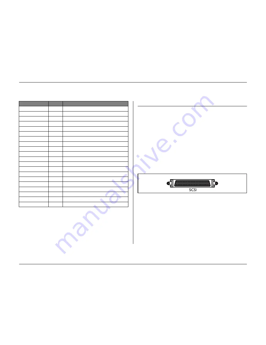
SCSI connection

The unit provides a 50-pin high density SCSI-2 port for connection of an 
external storage system, for example, a LP (DVAD) or a RAID (DVAS) storage 
array. To use this feature, connect the drive's SCSI cable to the SCSI-2 connector 
on the rear panel.  

Specification

Connector type:

50-pin narrow SCSI connector for external SCSI device 

Bus format:

Narrow (8 Bits) single-ended 

Max. number of SCSI devices: 7 

Max. transfer rate:

20 Mbytes per second

Total cable length:

Fast-20

1 to 4 SCSI devices

3m

5 to 7 SCSI devices

1.5m

Alarm_in_6

6

Alarm input 6

Alarm_in_7

7

Alarm input 7

Alarm_in_8

8

Alarm input 8

Alarm_in_9

9

Alarm input 9

Alarm_in_10

10

Alarm input 10

Alarm_in_11

11

Alarm input 11

Alarm_in_12

12

Alarm input 12

Alarm_in_13

13

Alarm input 13

Alarm_in_14

14

Alarm input 14

Alarm_in_15

15

Alarm input 15

Alarm_in_16

16

Alarm input 16

Relay1_A

17

Relay 1 output pole 1

Relay1_B

18

Relay 1 output pole 2

Relay2_A

19

Relay 2 output pole 1

Relay2_B

20

Relay 2 output pole 2

Relay3_A

21

Relay 3 output pole 1

Relay3_B

22

Relay 3 output pole 2

Relay4_A

23

Relay 4 output pole 1

Relay4_B

24

Relay 4 output pole 2

System Ground

25

Chassis Ground

Signal name:

Pin no.

Description

25

1

26

50

Panel view

Summary of Contents for Divar

Page 1: ...DIVAR DIGITAL VERSATILE RECORDER Installation Manual www philipscsi com ...

Page 2: ... 2003 Philips Electronics N V 2003 Philips Communication Security Imaging Inc All Rights Reserved Philips is a registered trademark of Philips Electronics N V Data subject to change without notice ...

Page 3: ...tion Security Imaging i Installation manual Chapters 1 Introduction 2 Quick install 3 Operating instructions 4 Hardware setup 5 Menu system 6 Using the Configuration Tool 7 Menu default values 8 Technical specifications ...

Page 4: ...ec weekend night 2 5 Enable alarm inputs for 2 5 Alarm input recording 2 5 Enable motion for 2 6 Motion recording 2 6 Approximate recording duration 2 6 Network settings 2 6 DHCP 2 6 DVR name 2 6 IP address Subnet mask and Default gateway 2 6 MAC address 2 6 Bandwidth limit 2 6 Operating instructions 3 1 Front panel controls 3 2 Indicators 3 2 Keys 3 2 Primary functions 3 3 Alternate functions 3 4...

Page 5: ...uences 5 7 Configure Monitors 5 7 System Settings 5 8 Recording Setup 5 8 Playback Setup 5 9 Event Setup 5 9 History Log Setup 5 10 Local Passwords 5 11 Connectivity 5 11 Licenses 5 12 Input and output contacts 5 12 Profiles 5 12 Calendar setup 5 12 Profile override 5 13 Profile manager 5 13 System behavior 5 13 Using the Configuration Tool 6 1 Getting started 6 2 System requirements 6 2 Installin...

Page 6: ...t into the outlet consult an electrician for replacement of the obsolete outlet 10 Protect the power cord from being walked on or pinched particularly at plugs convenience receptacles and the point where they exit from the apparatus SAFETY PRECAUTIONS This label may appear on the bottom of the unit due to space limitations Attention Installation should be performed by qualified service personnel o...

Page 7: ...nce dealer or local power company 17 Overloading Do not overload outlets and extension cords as this can result in a risk of fire or electric shock 18 Object and Liquid Entry Never push objects of any kind into this unit through openings as they may touch dangerous voltage points or short out parts that could result in a fire or electric shock Never spill liquid of any kind on the unit 19 Replacem...

Page 8: ...ultiscreen display Dwell time The length of time that an alarm indicator continues to operate after the event causing it has occurred The length of time a single image of a sequence is shown Full screen A display that only shows one picture occupying a full screen Multiscreen The division of a display screen so that it shows a certain number of cameras at the same time Sequence Camera pictures sho...

Page 9: ...ameras The recording rate and quality are selectable per camera All models have extensive alarm handling functions and telemetry control Alarm functions include motion detection in user definable areas of the image on any camera input The unit can be easily operated and programmed via the front panel control keys and on screen display menu system One monitor output provides full screen quad and mu...

Page 10: ...d output ports for keyboard connection and system expansion Dual monitor outputs Full screen and various multiscreen display capabilities in live and playback modes Spot monitor output with sequencing and OSD Motion detection 16 switching alarm inputs and 4 alarm outputs Video loss detection Audible alarm Pan tilt and zoom camera control Versions There are three Divar models 6 channel 9 channel an...

Page 11: ... for switching and alarm connections A 15 pin D type connector board with screw terminals used for PTZ connections Power supply cord Network cross over cable Serial RS232 cross over null modem cable Divar loop through cable Rack mounting kit A CD ROM with the software and the manuals Installation Environment Mounting The Divar is supplied as a desktop unit If desired the unit may be rack mounted u...

Page 12: ...posite video outputs 75 ohm BNC connectors and video coaxial cable for connecting the video signals AC power supply outlet for the unit that allows for secure isolation The unit has no on off switch for security reasons A keyboard KBD Digital PC for Control Center and Configuration Tool applications Pan tilt zoom control units SCSI cable for connection to external storage devices External storage ...

Page 13: ...s on how to quickly get the unit operational Make the connections described on the following pages and then enter the relevant data in the quick install menu The Quick Install menu appears the first time you start the unit When you have entered the relevant information the unit will be operational ...

Page 14: ...OUT VIDEO OUT VIDEO IN 1 6 3 11 2 7 5 4 9 8 1A 1B 2A 2B R E L A Y 3A 3B 4A 4B GND 1 2 GND 9 10 3 4 GND 11 12 5 6 GND 13 14 7 8 15 16 IN IN IN IN SHIELD CTRL 1 SHIELD SHIELD CTRL 2 SHIELD CTRL 3 SHIELD CTRL 4 SHIELD CTRL 5 110 240 Vac Storage Array PHILIPS A B DIVAR 390 Ohm AutoDome can be 6 9 or 16 depending on model ...

Page 15: ...ernal storage unit via the narrow 50 pin high density SCSI 2 port Powering up 10 Switch on all connected equipment 11 Connect the power cord to the unit First time use The unit starts with a multiscreen display The Quick install menu opens the first time you use the unit Fill in these basic settings to get the unit operational Select the Install item to save your settings and close the menu When y...

Page 16: ... selected Alarm Monitor Select the monitor on which input alarm messages are displayed Recording settings Opens recording settings submenu to fill in the basic recording settings for the day and weekend night profiles Network settings Opens network settings submenu to fill in the settings that control the behavior of the unit with respect to a network Save exit Select this item to load the setting...

Page 17: ...night Select the normal recording speed to be used for each of the activated cameras during the weekend night profile The Images Per Second IPS rates available for PAL range from Never 0 1 10 one image every 10 seconds up to 25 IPS The Images Per Second IPS rates available for NTSC range from Never 0 1 10 one image every 10 seconds up to 30 IPS Set the recording speed to NEVER to not record a came...

Page 18: ...e day one camera is in input alarm recording 5 of the time and every motion enabled camera is in motion recording 10 of the time During the night and weekend one camera is in input alarm recording 1 of the time and in motion recording for 3 of the time Network settings DHCP Set DHCP to Yes to have IP address subnet mask and default gateway assigned automatically by the network server The actual va...

Page 19: ...The instructions in this chapter explain the purpose of the front panel keys The functions available can be limited by setting passwords An administrator has access to many more functions in the menu Refer to Chapter 5 Advanced Menu Setup for a full list of available menu items ...

Page 20: ...n a camera signal Video loss flashes when a video loss condition is detected for a camera input Keys The keys on the front panel can be used for controlling primary functions or alternate functions Symbols for the primary functions are shown above the keys Symbols for the alternate functions are shown below the keys The alternate functions are activated by first pressing the ALT key and then the d...

Page 21: ...nd to protect recordings Play key in live mode press to resume playback from the last used playback position in pause mode press to resume playback Fast forward in live mode press to start playback from one minute earlier in playback mode press to speed up the playback rate in pause mode press to step forward one frame ACK key press when flashing to acknowledge an alarm Multiscreen key press to se...

Page 22: ...Up Down Right Select key selects a submenu or menu item or saves selections made in menus ESC key press to return to previous level or to exit menu system without saving press to leave help system Menu key opens the menu system Mon A key assigns front panel keys to monitor A Mon B key assigns front panel keys to monitor B Sequence key view cameras in sequence on full screen or quad displays Zoom k...

Page 23: ...tor B When multiple alarms or motion occur camera pictures are sequenced on monitor B Selecting a monitor to control To control the display on monitor A 1 Check that the light on the front panel is lit 2 If is not lit press the ALT key and then press the monitor A key To control the display on monitor B 1 Check that the light on the front panel is lit 2 If is not lit press the ALT key and then pre...

Page 24: ...electing a single camera also stops sequencing Cameo assignment Assigning cameras to cameos in a multiscreen view 1 Press the ALT key and then the multiscreen key The multiscreen key indicator flashes The border around the active cameo is green The camera key of the camera shown in the active cameo lights green 2 Use the arrow keys if you wish to select a different cameo 3 Press a camera key to di...

Page 25: ...3 Use the arrow keys to select the area of the picture to be displayed 4 Press the zoom key again to zoom in further The picture is enlarged by a factor of 4 5 Use the arrow keys to select the area of the picture you want to see 6 Press the zoom key again to return to a full picture and leave the zoom mode The zoom indicator no longer lights 7 Press the ALT key to return the keys to normal operati...

Page 26: ...n and again increases the display rate to a maximum and then back to normal speed again Press the rewind key in the pause mode to step back one field at a time Press the pause key to freeze the picture Press the forward key to start forward playback of recordings Pressing it again and again increases the display rate to a maximum and then back to normal speed again Press the forward key in the pau...

Page 27: ...s to see a list of results Press the escape key to exit the search mode and return to the previous mode SEARCH RESULTS The recording fitting the filter and closest to the start date and time is shown first Use the up down arrow keys to move through a long list The selected recording is shown Press the select key for a full screen playback of the selected recording Press the search key during playb...

Page 28: ... acknowledges the alarm situation The unit can react to an event in any one of the following ways Alarms A beeper sounds A status message is displayed An alarm icon is displayed The border around a cameo can change color An alarm indicator or flashes The indicator flashes An output relay is activated Alarms and Triggers The view modes on the monitors change A controllable camera is moved to a pre ...

Page 29: ...to be acknowledged If auto acknowledge is enabled the beeper and the alarm and indicators switch off after the dwell time Motion alarm If a motion detection signal causes an alarm Monitors A and B can switch to a pre programmed view mode Monitor A The border around the displayed cameos is yellow The motion icon is displayed in each cameo An alarm status message is displayed Monitor B Sequenced dis...

Page 30: ...ew mode is restored If the camera with video loss is visible the black cameo and the video loss message continue to be displayed as long as there is no video present If an alarm is not acknowledged the beeper and the video loss and indicators switch off after the dwell time but the alarm still needs to be acknowledged If auto acknowledge is enabled the beeper and the video loss and indicators swit...

Page 31: ... 1 CHAPTER 4 Hardware setup This chapter contains detailed information about the connection of external equipment to the unit The connector types and their pin signals are described All the connectors are located at the rear panel of the unit ...

Page 32: ...onnections Connect cameras to the unit using 75 ohm video coaxial cables with BNC connectors There are two BNC connectors for each camera Either connector can receive a camera s signal This signal is looped through directly connected to the other connector so that you can send the camera s signal to other equipment The camera input connectors are auto terminating so you do not need to add a termin...

Page 33: ...te video 1Vpp 75 Ohm Sync 0 3Vpp 10 Resolution 720 x 576 PAL 720 X 484 NTSC Connector type BNC Console port connection The serial RS232 console port connector is used to connect a PC to the unit for configuration or service purposes Use a null modem cable to connect the serial port of the PC to the unit The Baud rate can be selected in the menu system Specification Connector type 9 pole D type mal...

Page 34: ...s Belden 9841 or equivalent Divar connection The KBD IN and KBD OUT connectors can also be used to connect several Divar units to each other The loop through connector arrangement allows easy interconnection of up to 30 Divars The connection uses RS485 based communications Specifications Communicaton protocol RS485 Maximum signal voltage 12V Power supply 11 12 6V maximum 400mA Maximum cable length...

Page 35: ...lly if the network server uses DHCP Refer to the System settings Connectivity Network setup menu Specifications Connection 10 100 BaseT IEEE 802 3 Differential signal voltage 2 8V max inputs have transient overvoltage protection Port details IEEE 802 3 802 3u 100Base TX 10Base T physical layer Auto Negotiation 10 100 Full Half Duplex Cable length 100 Meters 100 Ohm unshielded twisted pair cable ca...

Page 36: ...ax Recommended cable Belden 8760 Number of loads per output 4 max Control port 15 pole D type socket SHIELD CTRL 1 SHIELD SHIELD CTRL 2 SHIELD CTRL 3 SHIELD CTRL 4 SHIELD CTRL 5 8 1 9 15 Panel view Signal name Pin no Description Code 1 1 Bi phase control ch 1 minus Code 1 2 Bi phase control ch 1 plus Shield 3 System ground cable shield Code 2 4 Bi phase control ch 2 minus Code 2 5 Bi phase control...

Page 37: ... or N C in the menu system The relays are active for the duration of the driving event Connect the application to the alarm output relays resistive loads only Do not exceed 30 Vac 40Vdc 500 mA continuous or 10VA on an alarm output relay s contacts The contacts must not be used at AC line voltages Specifications Alarm input impedence Internal pull up 10K to 5V Input voltage range 0 3V min to 30V ma...

Page 38: ...t 20 1 to 4 SCSI devices 3m 5 to 7 SCSI devices 1 5m Alarm_in_6 6 Alarm input 6 Alarm_in_7 7 Alarm input 7 Alarm_in_8 8 Alarm input 8 Alarm_in_9 9 Alarm input 9 Alarm_in_10 10 Alarm input 10 Alarm_in_11 11 Alarm input 11 Alarm_in_12 12 Alarm input 12 Alarm_in_13 13 Alarm input 13 Alarm_in_14 14 Alarm input 14 Alarm_in_15 15 Alarm input 15 Alarm_in_16 16 Alarm input 16 Relay1_A 17 Relay 1 output po...

Page 39: ...ns Loop through terminations Video levels of incoming signals and the possibility of ground loops Record for at least three minutes at the highest recording speed Then play back the recording selecting each camera for full screen display in turn Check the playback picture quality Check to see whether the programmed quality setting is adequate Maintenance Maintenance of this unit is limited to exte...

Page 40: ...Hardware setup 4 10 Philips Communication Security Imaging ...

Page 41: ...f you are using the unit in a stand alone configuration If you do have a PC connected to the unit or the unit is used in a network environment then the Configuration Tool offers a more convenient way of accessing and using the menu In both cases the parameters available are the same Slight differences in navigation and selection are only due to the differences between the keys on the unit and the ...

Page 42: ...t By spending some time in planning and setting up the six profiles available you can provide efficient use of resources while maintaining effective cover for most types of working situations Profiles are usually based on a calendar switching on and off at a particular date or time for example weekends or night Profiles can also be switched by an input signal based on an external switch or armed a...

Page 43: ... menu History Disk manager Time Date View settings System settings Profiles Advanced menus History View history list Disk manager Status overview Protected recordings Authenticity check Stop recording Storage setup Delete video Erase disk Time Date View settings Camera setup Sequences Configure monitors System settings Language Quick install Record setup Playback setup Event setup History log setu...

Page 44: ...recorded video and associated data is also accessed via this menu Access to some menus can be password protected Status Overview Disk Capacity shows the total space available in Gigabytes Used Space shows the total space used by all video recordings including protected recordings Protected Recordings Usage shows the space used by protected recordings that cannot be overwritten The displayed Record...

Page 45: ...s always logged in the history list Recording starts automatically when interrupt period has elapsed Storage setup Storage Setup gives an overview of internal and external storage The total disk space available is shown in Gigabytes Any new disks found are disabled by default Select the storage location you wish to enable or disable All recorded video is lost if you change a disk configuration If ...

Page 46: ...are displayed and the duration Use the Configure Monitors submenu to set up the monitor displays Camera setup Use the Camera Setup menu to access the submenus for setting the camera names for locking cameras and for controlling cameras Camera name Select a camera by pressing a camera key on the unit The number of the camera is the number of the connector at the rear of the unit to which it is conn...

Page 47: ...onds The default value is 5 seconds List Full screen monitor A The sequence list shows the order in which the camera images are displayed in full screen mode Use the arrow keys to select a position in the list Press a camera key on the unit to enter a camera number in the list Press F2 to clear the rest of the list Press F1 to restore all defaults Connected cameras are then listed in ascending ord...

Page 48: ... The quick install menu is described in Chapter 2 If you select Factory Defaults all settings in the menu system are reset to their default value Recording Setup The continuous mode overwrites older recordings when the disk is full You can set an overwrite protection period of up to 15 weeks for the latest recordings The linear mode first gives a warning and then stops recording when the disk is f...

Page 49: ...ch the triggered view mode is displayed after activation The value Follows activates the beeper and relay or view only as long as the event is present Input Setup To restore the default input settings select the Clear Input Settings item Select the Display Monitor submenu to choose the view mode and cameras to be displayed when an input is activated Select the number of the output relay to be acti...

Page 50: ...lected camera not necessarily the controllable camera Select up to four cameras to be displayed in sequence Motion area Select a camera number The motion indicator shows the maximum level of camera motion that has been detected for the defined area Press F2 to clear it if you want to re test the level of motion detection Use the arrow keys to adjust the Trigger level slider to just below the indic...

Page 51: ...addresses when DHCP is set to No The MAC address is read only Restrict the network bandwidth by entering an Mbps between 0 and 100 for the bandwidth limit Network access Access to the unit via the network can be set for up to six different users Restrict access to the unit by listing an IP address range The range you use will normally depend on your network setup Select a user number to set up the...

Page 52: ...s contacts to normally closed N C Press a camera key to place or remove a check mark PROFILES Six different profiles can be stored These profiles can be activated by an input switch or by a date or time The profiles contain configuration settings for recording data handling events and restricting access You can define a calendar that automatically selects profiles These profiles can be configured ...

Page 53: ...he Profile Manager lists the scheduled and active profiles The Profile Override Inputs submenu sets up the inputs to switch profiles The Profiles Titles submenu assigns names to the six different profiles Profile override inputs Six inputs can be set up to select a profile The active profile defined by the calendar and exception day schedule is overridden by the input selection as long as the inpu...

Page 54: ... record a camera at all No pre alarm recording is done and the camera cannot be viewed over the network Input Each input when activated can change the normal recording behavior of up to four cameras for a maximum of 120 seconds Select the profile Select the input number Select the cameras whose recording behavior should change Set the recording rates and quality levels for each camera Set camera n...

Page 55: ...Tool runs on a PC that is connected to the Divar either directly via an RS232 serial connection or via an Ethernet network connection Although all settings can also be configured with the on screen display menu of the Divar itself the Configuration Tool offers a very user friendly alternative It also allows configuration settings to be saved on the PC hard disk These can be restored later and used...

Page 56: ...e the Setup exe file on the CD and double click it 3 Follow the instructions on the screen and select to install the Configuration Tool when asked to complete the installation Starting the Configuration Tool Starting the Configuration Tool depends on how you are connected to the unit via a serial RS232 connection via a network or offline Serial connection If your PC is connected directly to the un...

Page 57: ...pe your user name and password The user name and password to be filled in are set in the System settings Connectivity Network access menu of the Divar itself 3 Click Login To modify the Divar list The Edit Divar list window allows you to add Divars to the list or delete Divars from the list To add a Divar to the list 1 Click Add 2 Enter the IP address or nickname of the new Divar The IP address to...

Page 58: ... is slightly different in the Configuration Tool The History menu item is removed from the menu tree structure and is now accessed via the Event log button The Disk manager submenu is replaced by the Storage setup item of the menu tree structure in the Configuration Tool As a result of the windows interface selection and editing of some functions with the Configuration Tool is different to the met...

Page 59: ...s you want to see Fill in the date time values to restrict the period for viewing events Uncheck those type of events that you do not wish to see The latest event is shown first If a date or time has been changed the original values are also displayed Press More to see more events Settings button Click the Settings button to display the menu for configuring the Divar The menu tree structure and th...

Page 60: ...d on the PC disk You can save as many of these files as you like just give them different names The settings in these files can be loaded back into the Configuration Tool either completely or in subgroups Although these files are stored as text files and can be viewed with a text viewer do not change or edit them as this makes them unusable Import 1 Click the import button to open a settings file ...

Page 61: ...he menu system Print When the Overview or Event log page is active you can print the complete contents of the page or list 1 Click the print button to print the current settings 2 Click OK to print Save When the Overview or Event log page is active you can save the complete contents of the page or list 1 Click the save button to save the current settings in a PC file 2 In the Save dialog box enter...

Page 62: ...Using the Configuration Tool 6 8 Philips Communication Security Imaging ...

Page 63: ...The table on the following pages lists the items of the menu system of the unit with default values The righthand column of the table gives the default values of these menu items These values are restored when the Factory defaults item of the System settings menu is selected ...

Page 64: ...r PAL 12 hour NTSC Date format YYYY MM DD Synchronize Use timer server No IP address 0 0 0 0 View Settings Camera setup Camera name Select input 01 16 Title CAMERA 1 CAMERA 16 Camera lock out Enter password only when set Camera list No cameras locked Set password No password set Camera control Auto camera contrast On Adjust contrast 0 Camera controllable No cameras selected Sequences List Fullscre...

Page 65: ...time date monitor B On Status position Bottom 0 Text intensity White clear Cameo border intensity Black Exit menu on alarms No System Settings Language English Recording Setup Record mode Continuous Overwrite protection None Pre event time 10 sec Disk Full Alarm Setup Disk Full warning 95 Disk Full alarm 1 min Output relay None Beeper Disable Playback Setup List of camera block after No block Even...

Page 66: ... B Camera pre positions None PP01 Motion Setup Output relay None Beeper Disable Video loss Setup Display monitor A Yes Display monitor B No Output relay Relay 2 Beeper Enable History log setup Log alarms Yes Log motions Yes Log video loss Yes Log errors Yes Log network Yes Connectivity Keyboard access Keyboard 1 Both Keyboard 2 Both Keyboard 3 Both Level 1 Level 2 Level 3 Level 4 Level 5 Default v...

Page 67: ...etwork access IP Range List of IP addresses 0 0 0 0 255 255 255 255 List of users User name ADMINISTRATOR USER2 6 User rights Playback User password No password Expand system DVR ID 1 First camera number 1 Com port Connect to CCL Baudrate 9600 Parity None Bits 8 Stopbits 1 RTS CTS On Licenses Simultaneous users 1 Level 1 Level 2 Level 3 Level 4 Level 5 Default value ...

Page 68: ...s Inputs alarm Enabled for connected cameras Motion enable Disable all Motion alarm Disable all Video loss enable Enabled for connected cameras Auto acknowledge alarms Yes Output handling Select profile 1 Relay enable Relays 1 and 2 enabled Beeper Enable Recording setup Normal List all cameras quality IPS Medium 1IPS Input Cameras not in alarm IPS No change Level 1 Level 2 Level 3 Level 4 Level 5 ...

Page 69: ... in alarm IPS No change Recording duration 15 seconds Access restrictions Select profile 1 Local playback password Disable User 2 Access User 3 Access User 4 Access User 5 Access User 6 Access Copy system behavior Copy from None Copy to None Advanced menus No Level 1 Level 2 Level 3 Level 4 Level 5 Default value ...

Page 70: ...Menu default values 7 8 Philips Communication Security Imaging ...

Page 71: ...Philips Communication Security Imaging 8 1 CHAPTER 8 Technical specifications The following pages give the technical specifications of the unit ...

Page 72: ...0 VAC 40 VDC 0 5A continuous 10VA Control RS232 Output signals according EIA TIA 232 F max input voltage 25V Keyboard input Conform RS485 max signal voltage 12V supply 11V 12 6V at max 400mA Keyboard output Conform RS485 max signal voltage 12V Bi Phase Impedance 128 ohm max overvoltage protection 40V max cable length 1 5km Connectors Video inputs 6 9 or 16 looping BNC auto terminating Ethernet RJ4...

Page 73: ...x 315 x 45 mm 17 4 x 12 4 x 1 8 inch Weight approx 5 8 kg 12 8 lbs Rack Mount Kit Included For mounting one unit in an EIA 19 inch rack Environmental Temperature Operating 0 C to 45 C 32 F to 113 F Storage 25 C to 70 C 13 F to 158 F Relative humidity Operating 93 non condensing Storage 95 non condensing Electromagnetic Compatibility EMC requirements USA FCC Part 15 Class B EU EMC directive 89 336 ...

Page 74: ...8 4 Philips Communication Security Imaging ...

Reviews: