GRL-PCIE5-CEM-RXA User Guide and MOI
Rev7.0
© Granite River Labs 2022 Version 7.0, June 2022. Updated 06.29.2022
Page 40 of 123
5.5
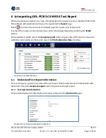
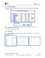
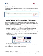
Set Up Automated DUT TxRx Link Equalization Test
Once calibration has been completed from Section 4, continue with the following setup to
perform initial link equalization (EQ) tests to prepare the DUT for the final stage of Rx compliance
testing. The setup requires the Anritsu MP1900A BERT (including the MU195040A SI Error
Detector), PCIe Gen 5 System Board or Add-In Card DUT, PCIe5 Re-Driver, and oscilloscope to be
used.
5.5.1
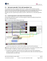
Connect Equipment for System Board TxRx Link EQ Testing
The following link EQ test setup uses a PCI-SIG compliance load board (CLB) test fixture for the
PCIe Gen 5 System Board DUT.
Note
: Use logical Lane 0 for the following test setup.
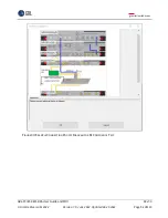
F
IGURE
27.
R
ECOMMENDED
S
ETUP FOR
DUT
T
X
R
X
L
INK
EQ
T
ESTING
(PCI
E
G
EN
5
S
YSTEM
B
OARD
)
Note
: Before starting the System Board TxRx Link EQ Test, make sure to perform optimization of the
Return Path (DUT Tx to BERT error detector). Refer to Appendix B or C for details.
1.
Using back the same BERT connections from the Long Channel system board calibration,
remove all Variable ISI channels and connect the Ref Clk of the CLB to the 100 MHz Ref Input on
the MU181000A/B with a BNC cable.


