GRL-PCIE5-CEM-RXA User Guide and MOI
Rev7.0
© Granite River Labs 2022 Version 7.0, June 2022. Updated 06.29.2022
Page 90 of 123
9.
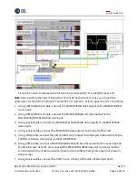
On the Scope, capture the Preset 0 waveforms and save to a file labeled as either
“Add In
Card_Ln00_TXResponse_P0X_d_acq000”
(for the add-in card where P0X represents the Preset
Number) or
“System Board_TXResponse_P0_d_acq000”
(for the system board). For example if
using a add-in card DUT, the Preset 0 waveform should be saved as
“Add In
Card_Ln00_TXResponse_P00_d_acq000”
. If using a system board DUT, the Preset 0 waveform
should be saved as
“System Board_TXResponse_P0_d_acq000”
.
10.
Repeat steps 1 to 8 for each Preset change.
11.
Repeat steps 1 to 9 for each Cursor change.
12.
Perform post processing analysis for each waveform to locate the transition time between the
preset/cursor change.
13.
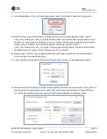
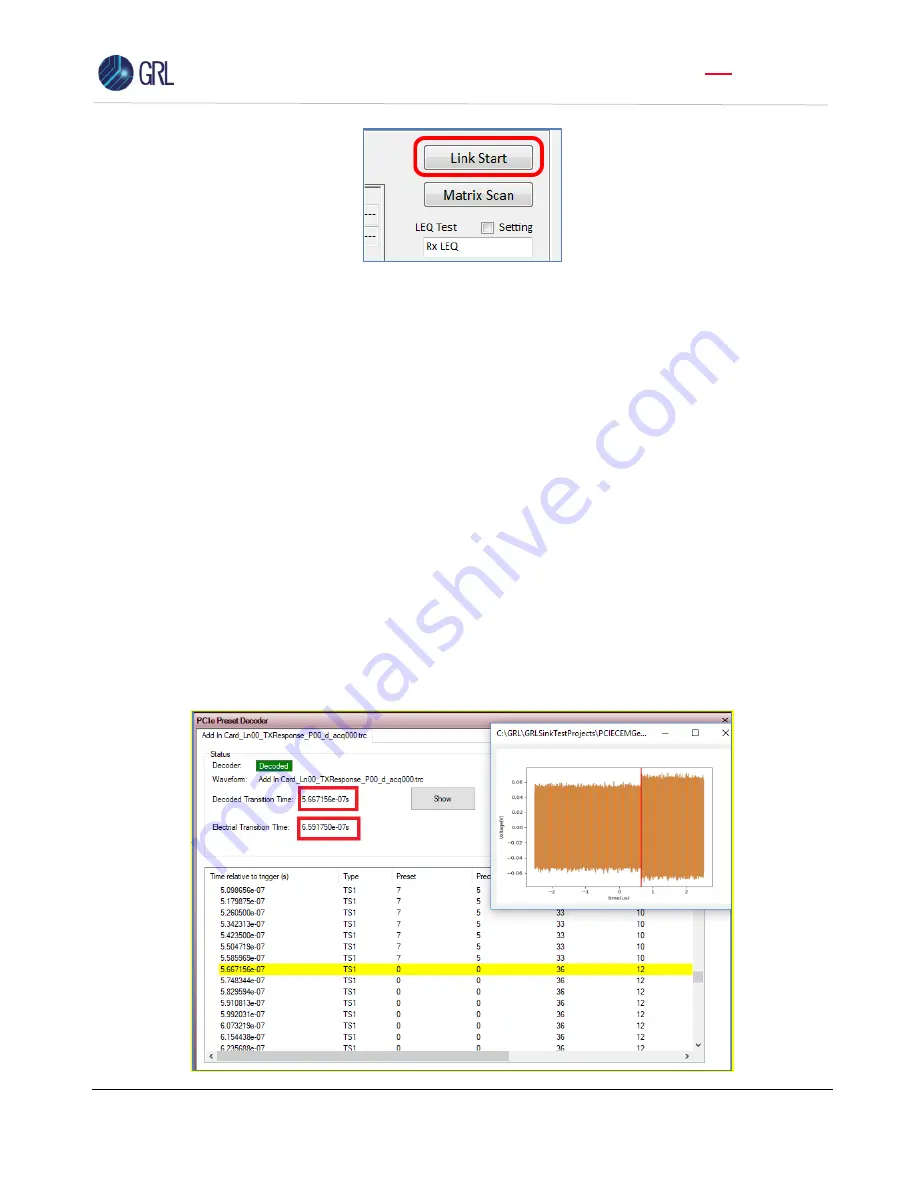
On the GRL software, go to the Setup Configuration page and select the Debug Tool tab. Select
either the
“Tx Response Preset” or “Tx Response
Cursor
”
button depending on which is being
tested. In the Select Waveforms pop-up window, select all the waveforms that were previously
captured and click
“
OK
”
.
14.
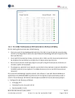
In the PCIe Preset Decoder screen, verify that the Electrical transition time is showing < 1 µs to
pass the test.
Note: The Decoded transition time serves as an informative value only and is not
required for compliance.

